Projector

a projector and projection screen technology, applied in the field of projectors, can solve the problems of color unevenness at the end and the center portion of the projected image, color unevenness, and contrast degradation

Active Publication Date: 2004-12-09
SEIKO EPSON CORP
View PDF7 Cites 18 Cited by
  • Summary
  • Abstract
  • Description
  • Claims
  • Application Information

AI Technical Summary

Benefits of technology

[0014] With this configuration, it is possible to reduce or prevent the contrast of a projected image from being degraded by reflecting and eliminating a predetermined spectral component using the optical filter to carry out spectrum correction.
[0045] With this configuration, a combined light combined in a color combining optical system passes through the optical filter to allow all color light components to be subject to spectrum correction, thereby obtaining a high definition projected image.

Problems solved by technology

However, there is a problem that even though the projector including the light source is intended to be used only in home, a white colored portion changes into white color adulterated with green color in a projected image, because of a strong appearance of a green color wavelength range.
This results in contrast degradation.
Accordingly, if the center of the optical path and the optical axis of the projection lens are matched to each other, the incident angle of the light flux, which forms an end portion of the projected image, increases with respect to the optical filter, resulting in color unevenness at an end portion and a center portion of the projected image.
Further, if the center of the optical path and the optical axis of the projection lens are not matched to each other, the incident angle of light, with respect to the optical filter, becomes larger as it becomes farther away from the optical axis of the projection lens, resulting in color unevenness at a portion intersecting with an extended line of the optical axis of the projection lens and at a portion most remote from that in the projected image.

Method used


Image

  • Projector
  • Projector
  • Projector

Examples


first exemplary embodiment

[0062] A. First Exemplary Embodiment

[0063] Hereinafter, the first exemplary embodiment of the present invention will be described with reference to the accompanying drawings.

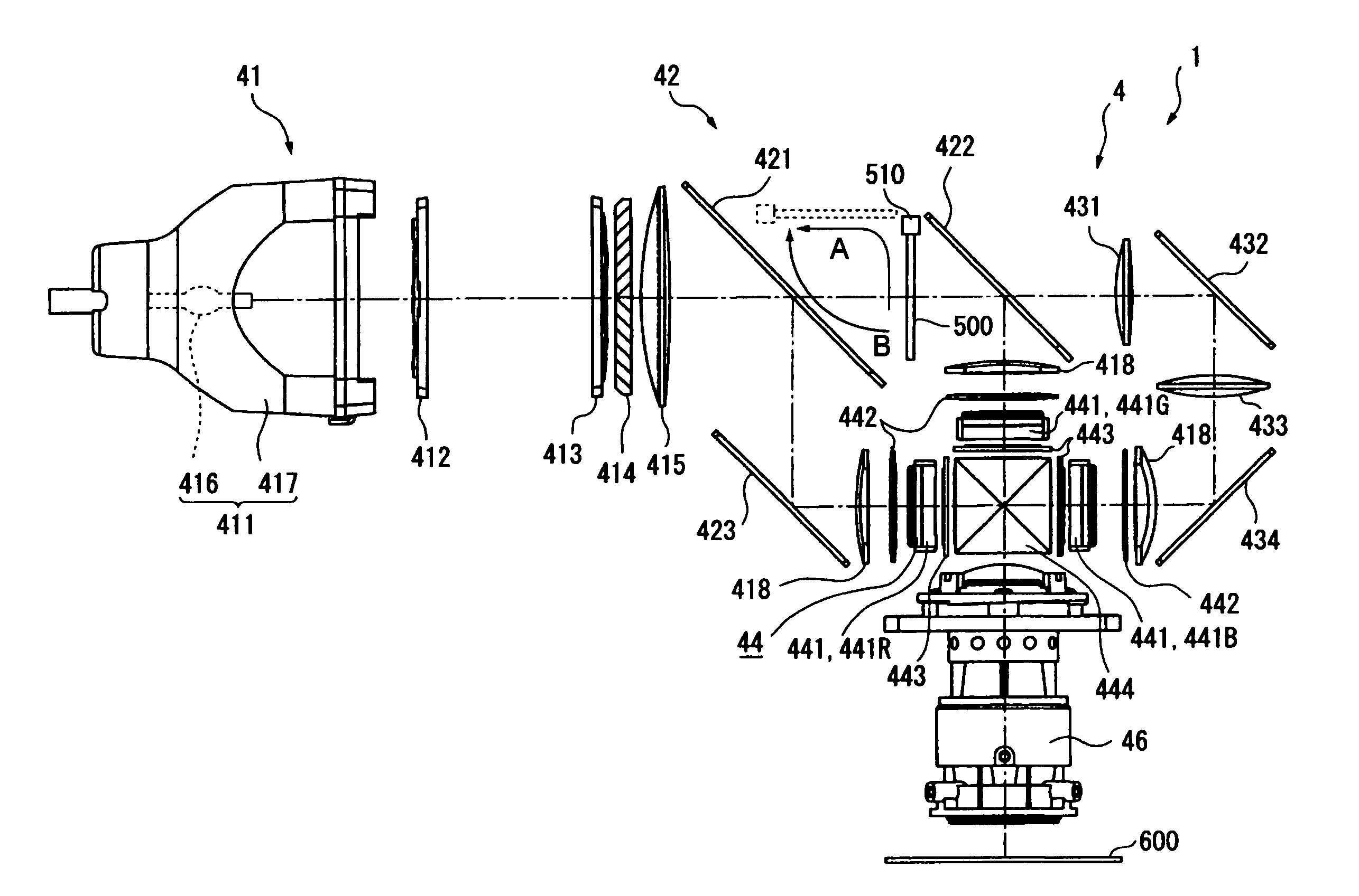
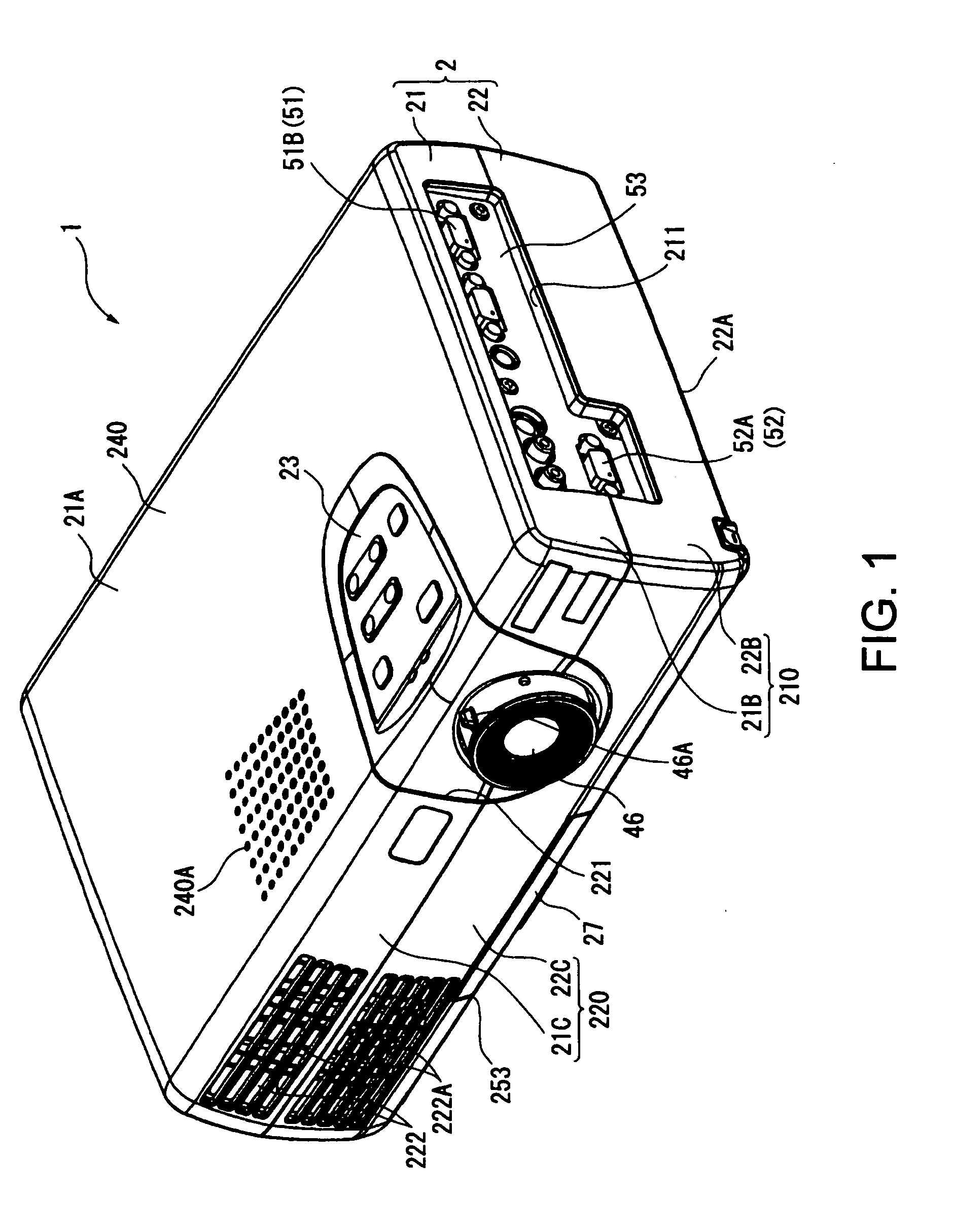
[0064] 1. Major Configuration of Projector

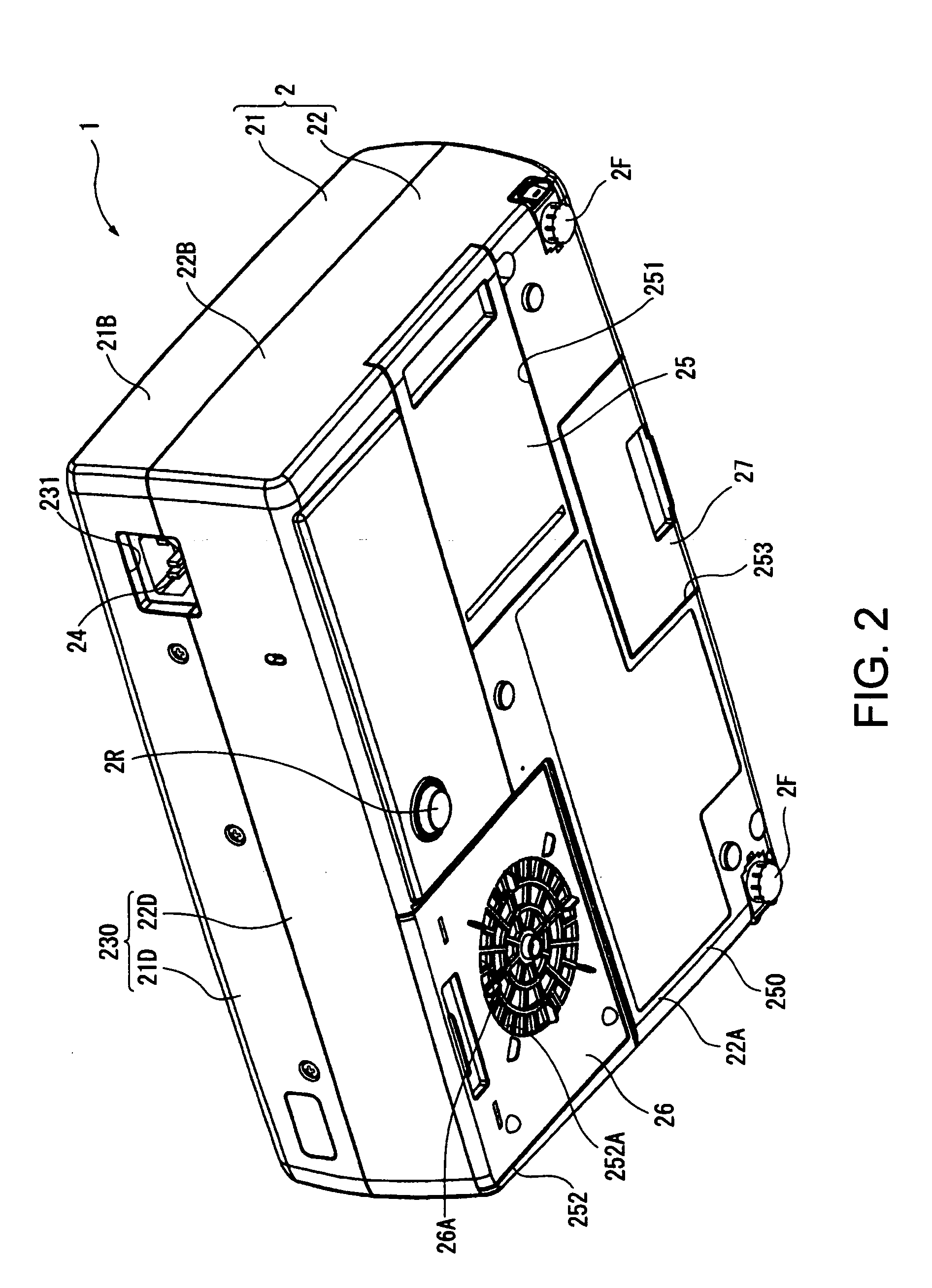
[0065] FIG. 1 is a schematic of a projector 1 according to the first exemplary embodiment of the present invention viewed from the top. FIG. 2 is a schematic of a projector 1 viewed from the bottom.

[0066] As shown in FIG. 1 or 2, the projector 1 includes a substantially rectangular parallelepiped external case 2 molded by injection molding. This external case 2 is a synthetic resin case to house a main body of the projector 1, and includes an upper case 21 and a lower case 22, which are configured to be detachable from each other.

[0067] The upper case 21, as shown in FIGS. 1 and 2, includes an upper face portion 21A, a side face portion 21B, a front face portion 21C and a rear face portion 21D constituting an upper face, a side face, a front face and a rear face of the p...

second exemplary embodiment

[0134] B. Second Exemplary Embodiment

[0135] A projector according to the second exemplary embodiment of the present invention is different from the projector 1 according to the first exemplary embodiment only in the arrangement of the optical filter 500A and selection property, and is substantially the same as the projector 1 according to the first exemplary embodiment in the other configurations. To this end, same reference numerals are given to the same and similar components as the first exemplary embodiment and the explanation thereon will be omitted or simplified.

[0136] FIG. 9 is a schematic showing an optical system of a projector according to the second exemplary embodiment of the present invention. Further, the solid line of FIG. 10 is a schematic showing the spectrum property (the same property as indicated by the solid line of FIG. 6) of the light source lamp 416. The dotted line of FIG. 10 shows the selection property of the optical filter 500A when light is incident to t...

third exemplary embodiment

[0142] C. Third Exemplary Embodiment

[0143] A projector according to a third exemplary embodiment of the present invention is different from the projector 1 according to the first exemplary embodiment only in the arrangement of an optical filter 500B and a moving mechanism 510B, and the selection property and configuration, and is substantially the same as that of the first exemplary embodiment in the other configurations. For this reason, same reference numerals are given to the same and similar components of the first exemplary embodiment and the explanation thereon will be omitted or simplified.

[0144] FIG. 11 is a schematic showing an optical system of a projector according to the third exemplary embodiment of the present invention. Further, the solid line of FIG. 12 is a schematic showing the spectrum property (the same property as indicated by the solid line of FIG. 6) of the light source lamp 416. The dotted line of FIG. 12 shows the selection property of the optical filter 500...


PUM


Abstract

A projector includes a light source, a color separating optical system, liquid crystal panels, a cross dichroic prism, and a projection lens, in which an optical filter is disposed to reflect a predetermined spectral component in the light flux between a dichroic mirror and a dichroic mirror where an angle by which the light flux expands falls within 20° with respect to an illumination optical axis L of the light flux on an optical path from the light source device to a light flux-emitting surface of the projecting lens. Thus, carrying out spectrum correction can reduce or prevent the contrast degradation of the projected image. Furthermore, it allows the difference of an incident angle to the light flux-incident surface of the light flux to be smaller, thereby reducing color unevenness.

Description

[0001] 1. Field of Invention[0002] The present invention relates to a projector, for example, that includes a light source device, a color separating optical system to separate a light flux emitted from the light source device into a plurality of color light components, a plurality of optical modulation devices to modulate the separated color light components respectively according to image information, a color combining optical system to combine the optical images modulated by the respective optical modulation devices, and a projection optical system to enlarge and project the combined optical image.[0003] 2. Description of Related Art[0004] Related art projectors have been used for presentations, home theaters, or the like. There is, for example, a projector with enhanced image quality, including a light source device, a color separating optical system to separate a light flux emitted from the light source into a plurality of color light components, three optical modulation device...

Claims


Application Information

Patent Timeline
Patent Type & Authority Applications(United States)
IPC IPC(8): G03B21/00G03B21/14H04N9/31
CPCH04N9/3105H04N9/3197H04N9/315G03B21/00G03B21/14
Inventor OGAWA, YASUNORINAKANO, HIROHISA
Owner SEIKO EPSON CORP
Why Eureka
Try Eureka