Optical device and projector

a technology applied in the field of optical devices and projectors, can solve problems such as likely causes, and achieve the effect of avoiding pixel shift of projected images and obtaining high-quality images

Active Publication Date: 2005-03-15
SEIKO EPSON CORP
View PDF16 Cites 18 Cited by
  • Summary
  • Abstract
  • Description
  • Claims
  • Application Information

AI Technical Summary

Benefits of technology

According to the above aspect of the present invention, since the above-described optical device is provided, the position of the optical modulator after the p

Problems solved by technology

Consequently, the thermal stress unstabilizes the connection between the pin and the holding frame or the color-combining optical element, so that a pixel shift on account of mutual positio

Method used


Image

  • Optical device and projector
  • Optical device and projector
  • Optical device and projector

Examples


embodiment

(6) Modification of Embodiment

Incidentally, the scope of the present invention is not restricted to the above embodiment, but includes following modifications.

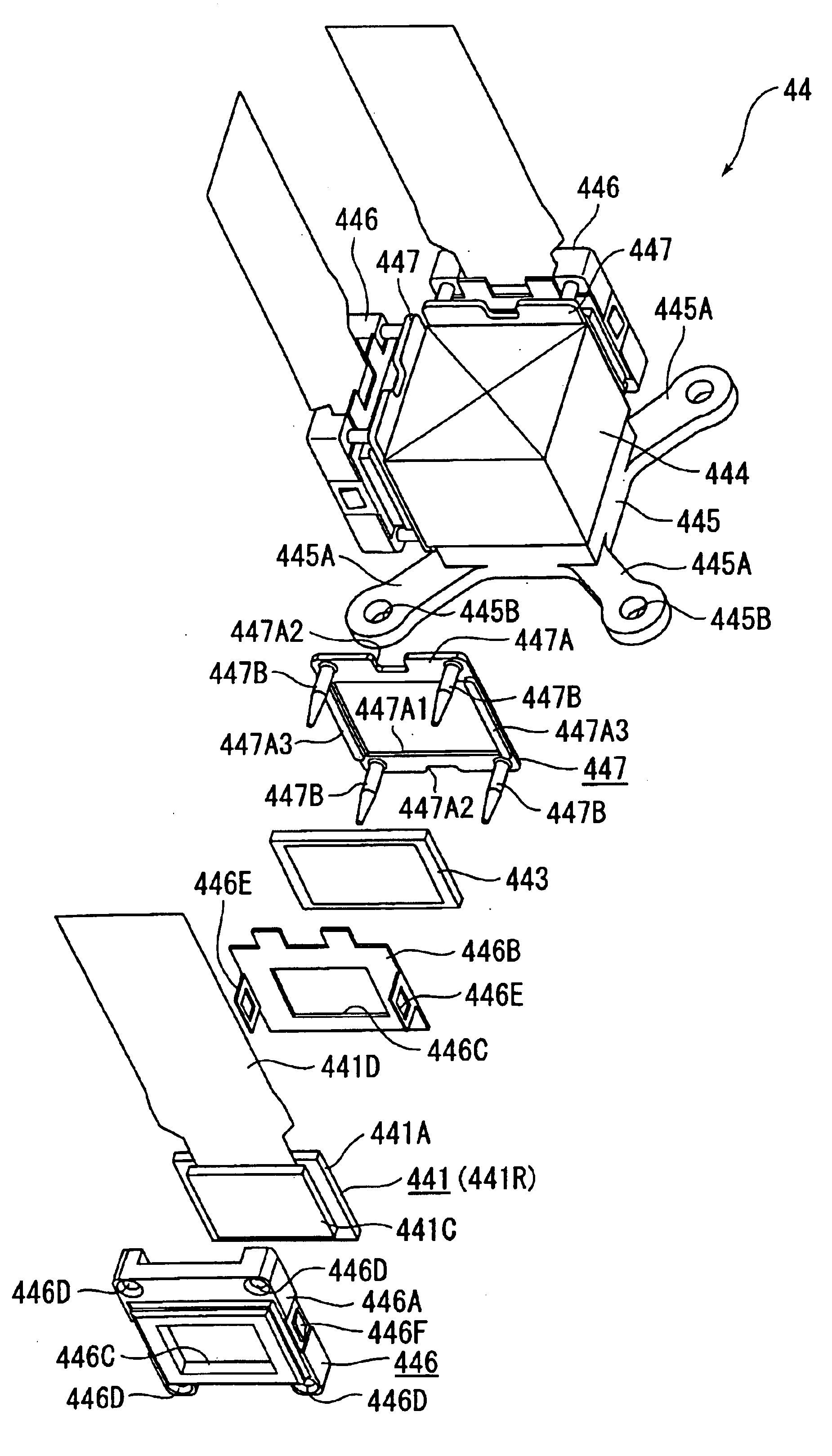
Though the panel fixing plate 447 is constructed of integrating the rectangular plate body 447A and the pin 447B in the above embodiment, different arrangement is possible. For instance, the pin 447B may be solely used as the panel fixing plate. At this time, since the pin 447B has the thermal expansion coefficient lying midway between the thermal expansion coefficients of the holding frame 446 and the cross dichroic prism 444, the thermal stress generated on the boundary of the holding frame 446 and the cross dichroic prism 444 can be reduced. Accordingly, the position shift of the liquid crystal panel 441 can be avoided.

Though the panel fixing plate 447 is molded by injection-molding in the above embodiment, different arrangement is possible. For instance, the panel fixing plate 447 may be formed by blow-molding and vacuum f...


PUM


Abstract

An optical device (44) has a holding frame (446) that holds a liquid crystal panel (441) as an optical modulator and has an opening (446C) at a part corresponding to an image formation area of the liquid crystal panel (441), and a panel fixing plate (447) disposed between the holding frame (446) and a cross dichroic prism (444). The panel fixing plate (447) is made of a component having a thermal expansion coefficient lying midway between the thermal expansion coefficients of the holding frame (446) and the cross dichroic prism (444). The liquid crystal panel (441) is fixed on a side of the cross dichroic prism (444) through the holding frame (446) and the panel fixing plate (447). Accordingly, a thermal stress generated on the boundaries between the panel fixing plate (447), and the holding frame (446) and the cross dichroic prism (444) are reduced, thereby preventing the position shift of the liquid crystal panel (441).

Description

FIELD OF THE INVENTIONThe present invention relates to an optical device and a projector.BACKGROUND ARTConventionally, projectors having a plurality of optical modulators respectively for modulating a plurality of color lights in accordance with image information, a color-combining optical element for combining the respective modulated color lights to form an optical image, and a projection lens for enlarging and projecting the formed optical image have been used.In such projectors, a color-separating optical system such as a dichroic mirror separates a light beam irradiated by a light source into three color lights. Three optical modulators such as liquid crystal panels respectively modulate the color lights in accordance with the image information. The color-combining optical element such as a cross dichroic prism combines the modulated color lights to form an optical image. Finally, the projection lens enlarges and projects the optical image.The respective optical modulators of s...

Claims


Application Information

Patent Timeline
IPC IPC(8): G03B21/16
CPCG03B21/16
Inventor ITO, SHINSUKETAKIZAWA, TAKESHI
Owner SEIKO EPSON CORP
Why Eureka
Try Eureka