Manufacturing method for material for ring rolling

Active Publication Date: 2016-09-22
HITACHI METALS LTD
View PDF3 Cites 3 Cited by
  • Summary
  • Abstract
  • Description
  • Claims
  • Application Information

AI Technical Summary

Benefits of technology

[0027]According to the present invention, a material for ring rolling capable of yielding the following effect can be easily manufactured. In the material for ring rolling obtained by the present invention, as a result of ring rolling being performed by using the material for ring rolling having the features described above, the free space for deforming the material for ring rolling can be secured by the height reducing portion. Accordingly, heating that occurs when the ring rolling is performed, is decreased, growth of crystal grains which may occur due to abnormal heating, can be suppressed, and therefore, a high-quality ring can be obtained. In addition, missing a part of the material on the inner diameter side, which may occur when the rolling is finished, can be reduced, and therefore, a high-quality ring having an extremely accurate shape can be obtained.
[0028]As a result, when producing a ring used in high temperature environments in which it is necessary to control sizes of crystal grains during ring rolling, the rolling can be completed within an appropriate temperature range. Accordingly, occurrence of a non-fine metal structure, which is caused by the growth of the grains, can be suppressed, and therefore, a shaped element of a high-quality ring includin

Problems solved by technology

On the other hand, the turbine disks and the blades in the gas turbine are used while being rotated at high speed, and therefore, there is a problem in that they are subjected to high loads which are applied due to centrifugal force during an operation of the gas turbine.
Furthermore, if they are used in an operation pattern in which start and stop of the operation of the gas turbine occurs intermittently, components of the tur

Method used


Image

  • Manufacturing method for material for ring rolling
  • Manufacturing method for material for ring rolling
  • Manufacturing method for material for ring rolling

Examples


examples

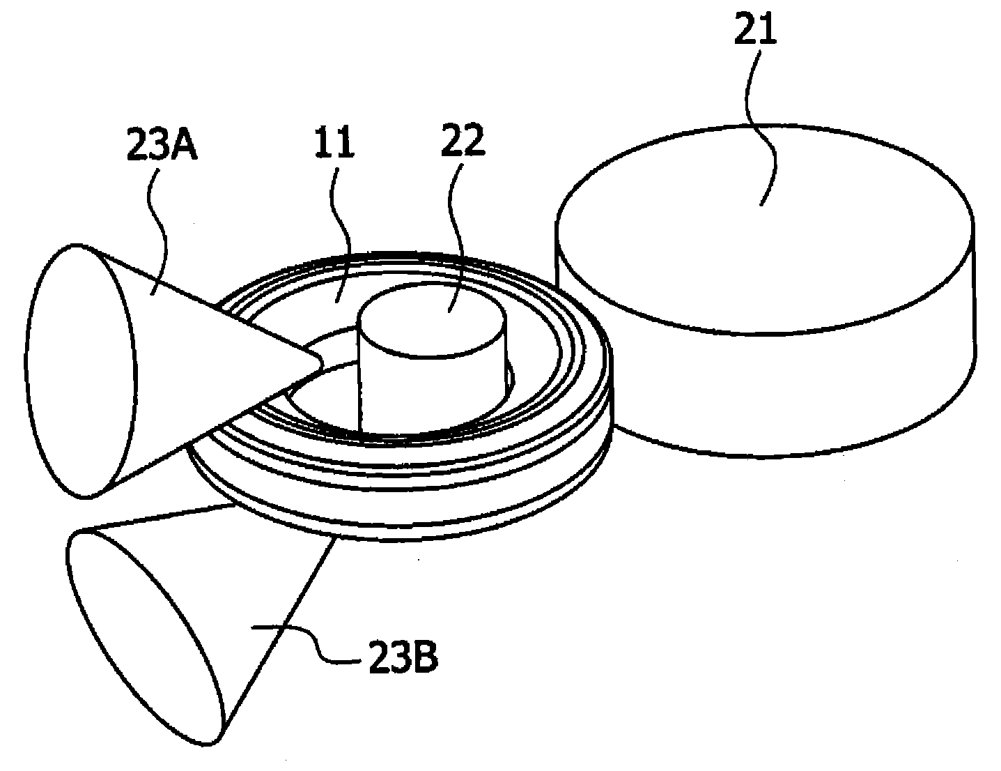
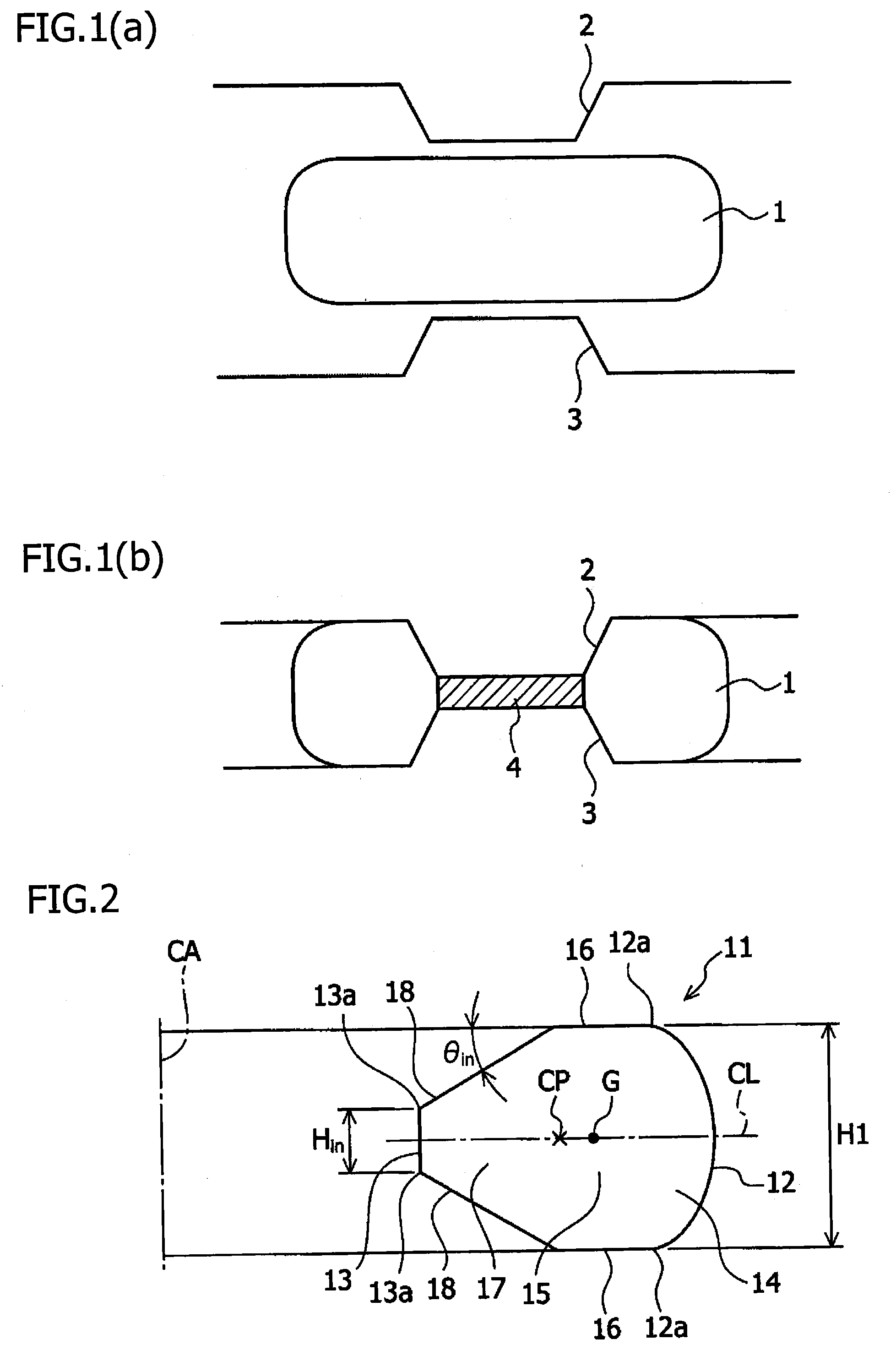
[0097]For an alloy equivalent to a 718 alloy used for a disk for a gas turbine of a diameter of Φ1000 mm or larger, the forming method of the material for ring rolling shown in FIG. 1, was applied to form the material 11 for ring rolling shown in FIG. 2. A hot forging temperature for the alloy equivalent to the 718 alloy was set at 920 degrees C. For the shape of the dies used in the Example, the upper and the lower dies shown in FIG. 6 were used. The angle of the convex portion with the truncated conical shape (θ) was 32 degrees.

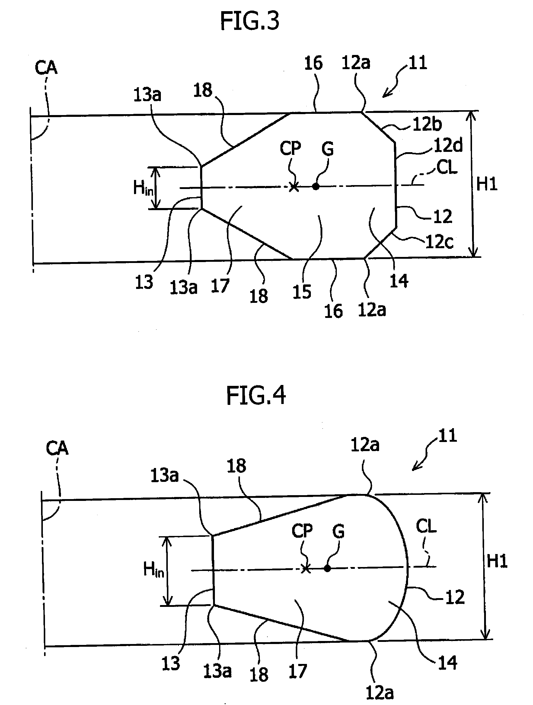
[0098]The dimensions of the material 11 for ring rolling were set so as to be the values shown in Table 1. Specifically, the outer peripheral portion 14 of the material 11 for ring rolling in contact with the main roll was shaped so as to have the curved surface shape tapered toward the outer periphery. The shape of the half section of the material 11 for ring rolling included the height reducing portion 17 formed so as to reduce the height from the center ...


PUM

PropertyMeasurementUnit
Fractionaaaaaaaaaa
Fractionaaaaaaaaaa
Thicknessaaaaaaaaaa

Abstract

A manufacturing method provides a high-quality material for ring rolling. The manufacturing method of the material for ring rolling includes a step of heating a disk-shaped material for hot forging to a hot working temperature, a step of arranging the material for hot forging onto a lower die having a convex portion with a truncated conical shape, a step of forming a thin portion by pressing a center portion of the material for hot forging by using an upper die having a convex portion with a truncated conical shape, and a step of manufacturing a material for ring rolling by removing the thin portion wherein a center of gravity on a half section of the material for ring rolling is located so as to be closer to an outer peripheral surface of the half section than a center of the half section in a thickness direction of the half section.

Description

TECHNICAL FIELD[0001]The present invention relates to a manufacturing method for a material for ring rolling to be shaped by rolling, the material for ring rolling to be used in high temperature environments.BACKGROUND ART[0002]A gas turbine is an example of an apparatus that uses a large number of components, such as heat-resistant steel components, superalloy components, and the like. In the gas turbine, wing-shaped blades are arranged on outer peripheries of a plurality of ring-shaped turbine disks, and an axial flow of fluid (i.e., a flow in an axial direction of a rotational shaft) is converted into rotary motion to generate power.[0003]Air is taken in from a front of the gas turbine and is then compressed by multistage axial flow compressing units which are downstream thereto. Furthermore, gas including a mixture of compressed air and fuel is burned in a combustion chamber which is further downstream thereto, to generate high-temperature and high-pressure combustion gas. This ...

Claims


Application Information

Patent Timeline
IPC IPC(8): B21H1/06F01D5/06
CPCF01D5/06B21H1/06B21J5/022B21K1/761B21J1/025C22C19/055C22C19/056C22F1/10B21J1/02B21J5/02C22C19/05B21B45/004B21D19/04F01D5/02F01D25/005F05D2220/32
Inventor YAGAMI, TETSUYATERAMAE, TOSHIYAFUJITA, ETSUONAGAO, SHINYAMUKOUSE, REMIIWASA, NAOYUKIFUKUI, TSUYOSHIAOKI, CHUYA
Owner HITACHI METALS LTD
Why Eureka
Try Eureka