Optical arrangement for non-inverting illumination system

a non-inverting, illumination system technology, applied in the field of optical systems, can solve the problems of color shift and light intensity of the different colors, system is relatively complex compared to conventional three imager parallel color, and additional problems, so as to avoid or avoid the influence of small flatness errors, the effect of reducing the chance of errors

Active Publication Date: 2005-08-25
BARCO NV
View PDF3 Cites 17 Cited by
  • Summary
  • Abstract
  • Description
  • Claims
  • Application Information

AI Technical Summary

Benefits of technology

[0024] It is a specific advantage of the present invention that the optical recombination system is based on an x-cube, thereby avoiding or at least reducing the use of mirrors on the light paths downstream the light modulating means and thus avoiding strong influences of small errors in flatness which may occur in the mirrors. It is a specific advantage of the present invention that the color beams are combined in a single optical component, thereby reducing the chance of errors introduced by shift of multiple optical components with respect to each other.
[0025] It is a specific advantage of the present invention that for each color, the image on the light valve has an equal magnification and has an equal sign of magnification, i.e. that either none of the color images is inverted or all of the color images are inverted.
[0026] Although there has been constant improvement, change and evolution of devices in this field, the present concepts are believed to represent substantial new and novel improvements, including departures from prior practices, resulting in the provision of more efficient, stable and reliable devices of this nature.
[0027] The teachings of the present invention permit the design of improved methods and apparatus for optical systems for projection systems.

Problems solved by technology

Nevertheless, as no convergence of the different color beams is performed, the system is relatively complex compared to conventional three imager parallel color systems.
This leads to additional problems with color shift and light intensity of the different colors in the illumination beam as after modulation the different color beams need to pass different and a different number of dichroic mirrors in order to form one single illumination beam.
This system also does not comprise an X-cube and therefore recombination of the different color beams needs to be performed by different dichroic mirrors, leading to additional problems with color shift and light intensity of the different colors.

Method used


Image

  • Optical arrangement for non-inverting illumination system
  • Optical arrangement for non-inverting illumination system
  • Optical arrangement for non-inverting illumination system

Examples


second embodiment

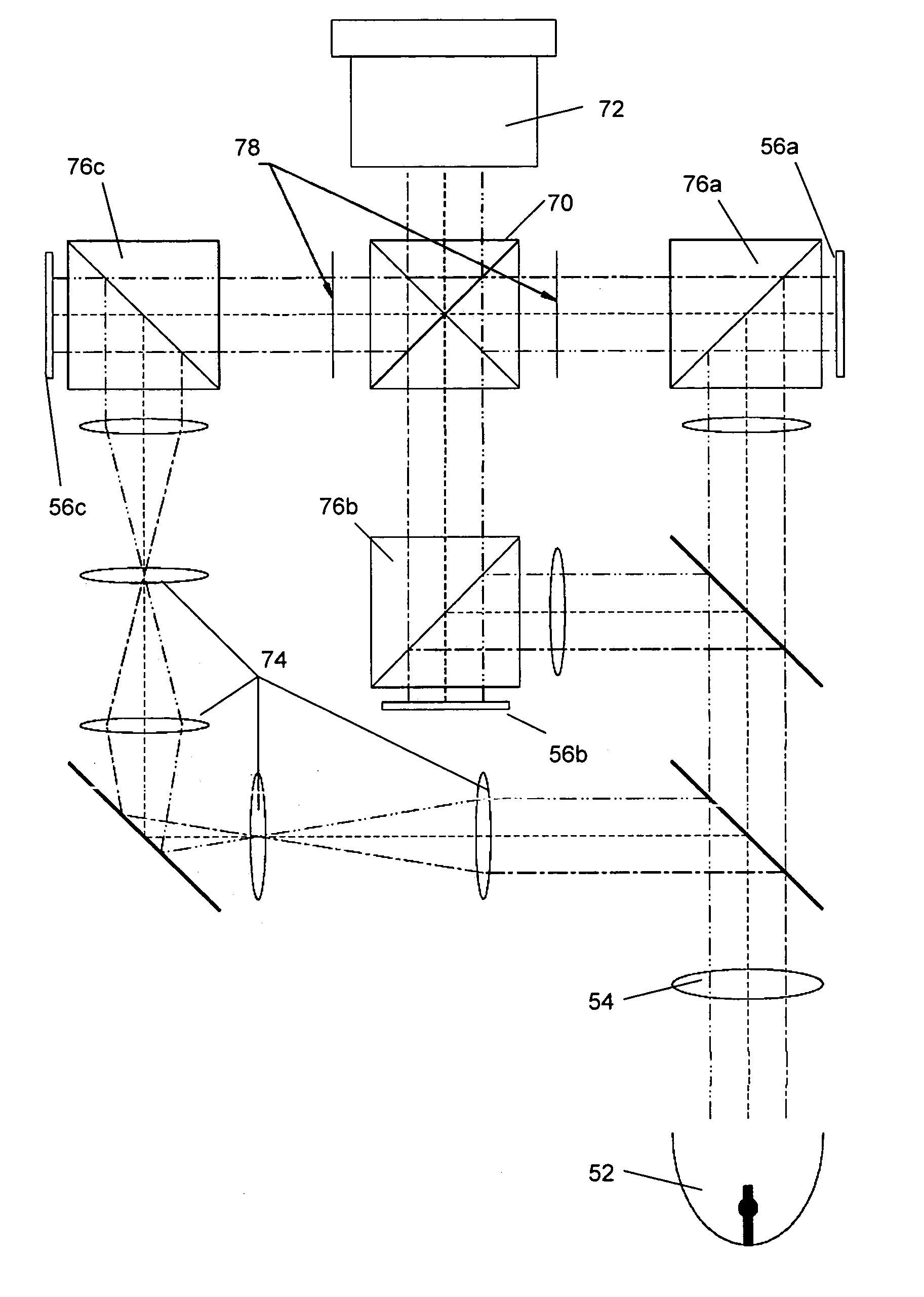
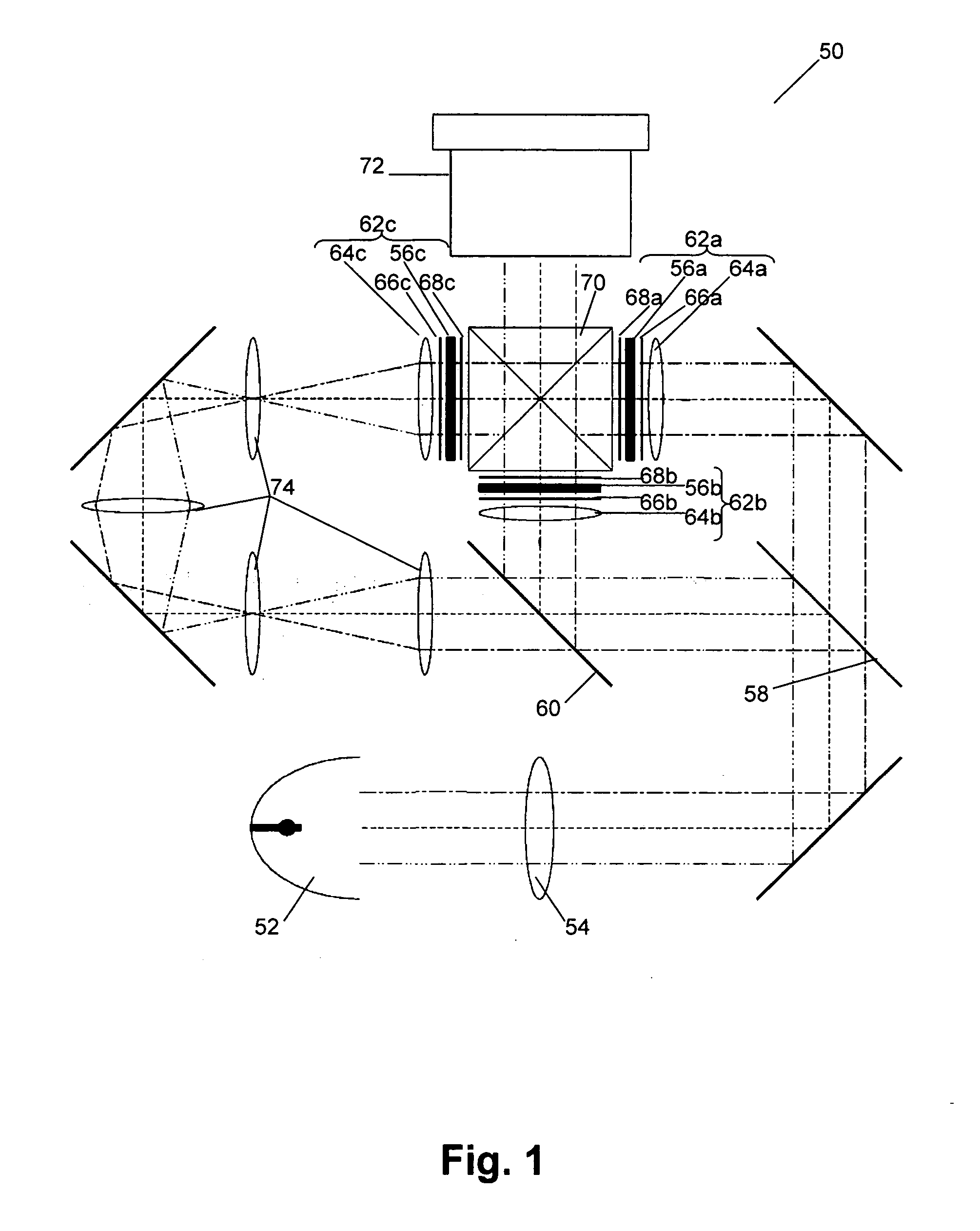
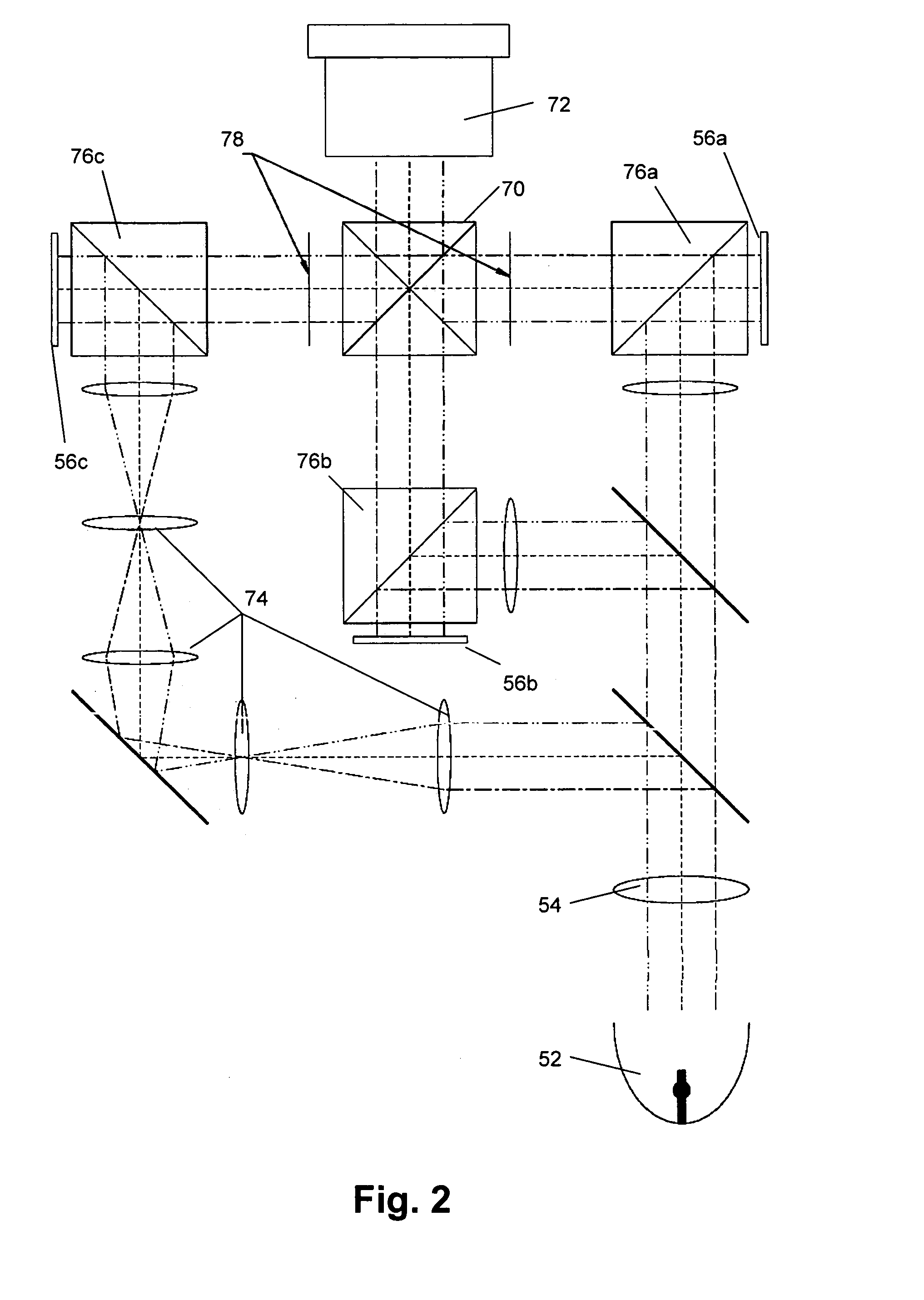
[0052] In FIG. 4 a schematic representation of an optical system for a projection system 100 according to the present invention is shown. The projection system comprises a light source 52, a number of optical components, a number of light modulating means 56 for forming an image for a corresponding number of color subbeams which are created, an X-cube 70 for recombining the color subbeams and a projection lens 72 for projecting the images on a screen. According to the present invention, the images of the color subbeams projected onto the light modulating means 56 have the same magnification and the same orientation. The differences in magnification between the sizes of the different color images are preferably smaller than 5%, more preferably smaller than 1%, most preferably smaller than 0.5%. In this embodiment, this is performed by providing equal light paths for all color subbeams. With equal light paths, it is meant that the distances between the imaging lens or imaging lenses a...

first embodiment

[0060] Additionally, the discoloration, i.e. the inhomogeneity in color or color shifts, on the screen also can be reduced further by taking into account the number of mirrors that are used for each of the color beams. As discussed in the first embodiment and shown in FIG. 3, the color inhomogeneities can be further reduced if the number of mirroring parts for each of the colors is all even or all odd. Also the mirror in the X-cube has to be taken into account. The distance between the color coordinates of a point left and a point right of an image that in principle displays one color, i.e. the image left-right color shift, for a system providing equal path lengths according to the present embodiment of the invention, is 0.0064. This is less than half the left-right color shift of a conventional system (0.013). This is also shown in Table 1.

[0061] It is a specific advantage of the current invention that in a non inverting illumination system, which may also include double inversion,...


PUM


Abstract

An optical design is described to be used in a color projection system. The system comprises a white light source (52), a light splitting means to split the white beam into color subbeams, optical components to direct each color subbeam on a light modulating means (56) and a dichroic prism (70). The light splitting means and the optical components are arranged such that each of the images of the color subbeams imaged on the light modulating means (56) has equal size and orientation, i.e. such that the magnification of the color subimage on the light modulating means (56) is equal. This is obtained by providing equal light paths for each color subbeam or by providing optical components such that either all different color images on the screen are inverted or none of the different color images are inverted.

Description

TECHNICAL FIELD OF THE INVENTION [0001] The present invention relates to an optical system and methods of operating the same for a projection system. More specifically the present invention relates to an optical system and method of operating the same for a color projection system having a good throughput efficiency and good color uniformity. BACKGROUND OF THE INVENTION [0002] Large-screen, high-brightness electronic projection display apparatuses serve different broad areas of application: electronic presentations for e.g. business, education and advertising, entertainment for e.g. home theatre and electronic cinema, display of status and information for e.g. military, utilities and transportation, simulation in e.g. training and games. In all these areas the need to correctly display color images is large. [0003] Electronic projection display apparatuses typically are based on one of three major technologies: CRT, liquid crystal display (LCD) technology or digital light processing...

Claims


Application Information

Patent Timeline
Patent Type & Authority Applications(United States)
IPC IPC(8): H04N9/31
CPCH04N9/3105H04N9/3197H04N9/317
Inventor BOSSCHE, BART VAN DENBEYERS, KOENBELLE, KOEN VANMEERLEER, PETER DE
Owner BARCO NV
Why Eureka
Try Eureka