Cooling mechanism of optical modulator, optical modulator attachment unit and projector

a cooling mechanism and optical modulator technology, applied in the field of cooling mechanism of optical modulator, optical modulator attachment unit and projector, can solve the problems of optical modulator, optical modulator, optical modulator,

Inactive Publication Date: 2002-03-28
SEIKO EPSON CORP
View PDF0 Cites 18 Cited by
  • Summary
  • Abstract
  • Description
  • Claims
  • Application Information

AI Technical Summary

Benefits of technology

[0015] According to the present invention, since the support member for supporting the optical modulator is formed by a pair of components disposed parallel to the cooling air flow channel formed between the light-incident end of the prism and the optical modulator for supporting the neighborhood of the end of the optical modulator, the gap between the light-incident end of the prism and the optical modulator facing the cooling air flow channel can be enlarged, so that cooling air sufficient for cooling the polarizer and the optical modulator can be flowed in the direction of the cooling air flow channel. Accordingly, the polarizer and the optical modulator can be efficiently cooled.
[0046] Accordingly, the wind guide can be more easily formed as compared to an arrangement where the wind guide is independently provided in accordance with respective optical modulator, so that the wind guide can be easily assembled to the optical modulator.

Problems solved by technology

The polarizing film can be deteriorated on account of heat generated by the light passing the prism and the optical modulator after long use and projected image quality can be deteriorated in accordance therewith.
On the other hand, since the optical modulator is also weak in heat, the optical modulator has to be cooled by cooling air.
However, only a narrow gap is formed between the prism and the optical modulator in accordance with size reduction, even when cooling air is sent from lower side of the prism by, for instance, a suction fan etc., only a little air enters between the prism and the optical modulator, so that efficient cooling of the polarizer and the optical modulator is difficult.
Since the cooling air exhausted from the axial fan flows in spiral, the cooling air is blown to the surface of the optical modulator obliquely upward, so that it is difficult to uniformly cool the surface of the optical modulator.
Since the air discharged from the axial flow fan flows in spiral, the cooling air blows the surface of the optical modulator obliquely upward, so that it is difficult to send the cooling air toward, for instance, corners of the optical modulator.
Further, though the structure of the holding frame can be complicated for forming a guide on the holding frame for guiding the wedge-shaped spacer in the arrangement disclosed in the International Publication No.
Since the air discharged from the axial flow fan flows in spiral, the cooling air blows the surface of the optical modulator obliquely upward, so that it is difficult to send the cooling air toward, for instance, corners of the optical modulator.

Method used


Image

  • Cooling mechanism of optical modulator, optical modulator attachment unit and projector
  • Cooling mechanism of optical modulator, optical modulator attachment unit and projector
  • Cooling mechanism of optical modulator, optical modulator attachment unit and projector

Examples


Embodiment Construction

)

[0059] An embodiment of the present invention will be described below with reference to attached drawings.

[0060] [1. Primary Arrangement of Projector]

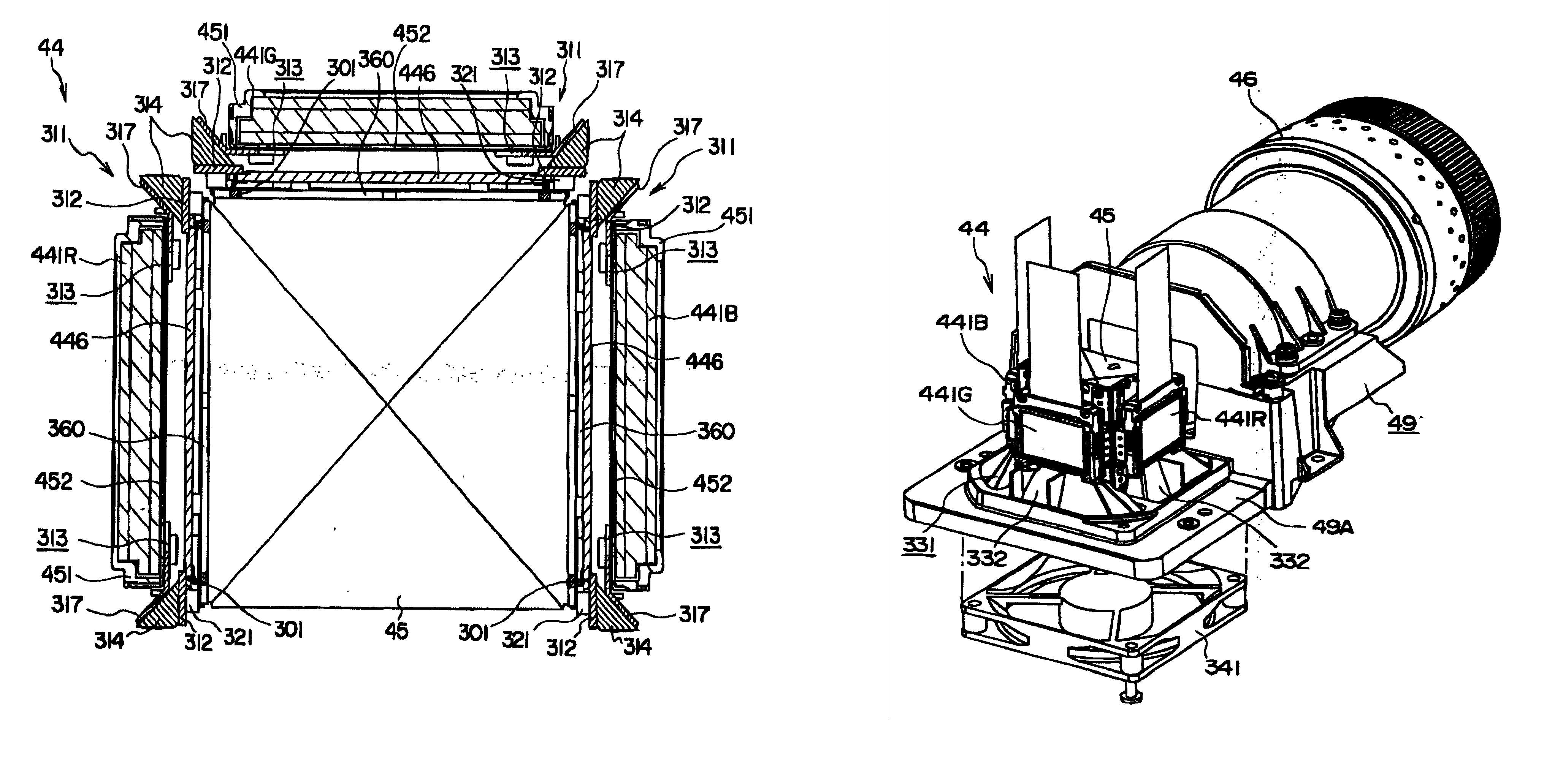
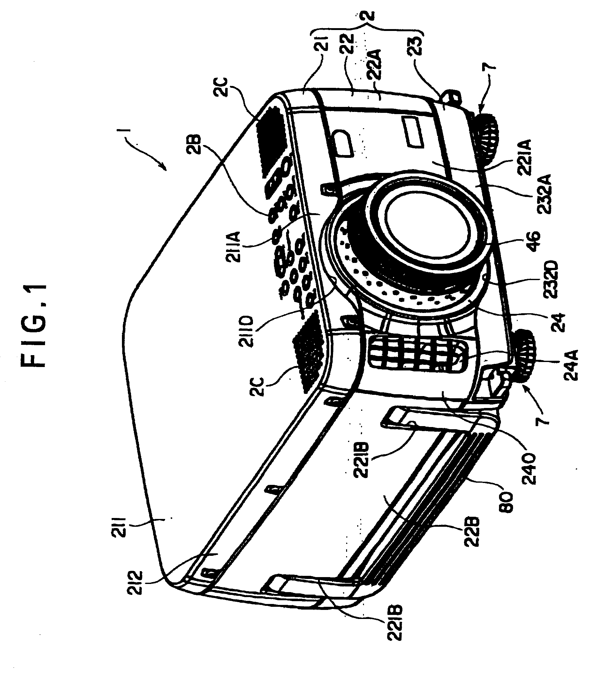
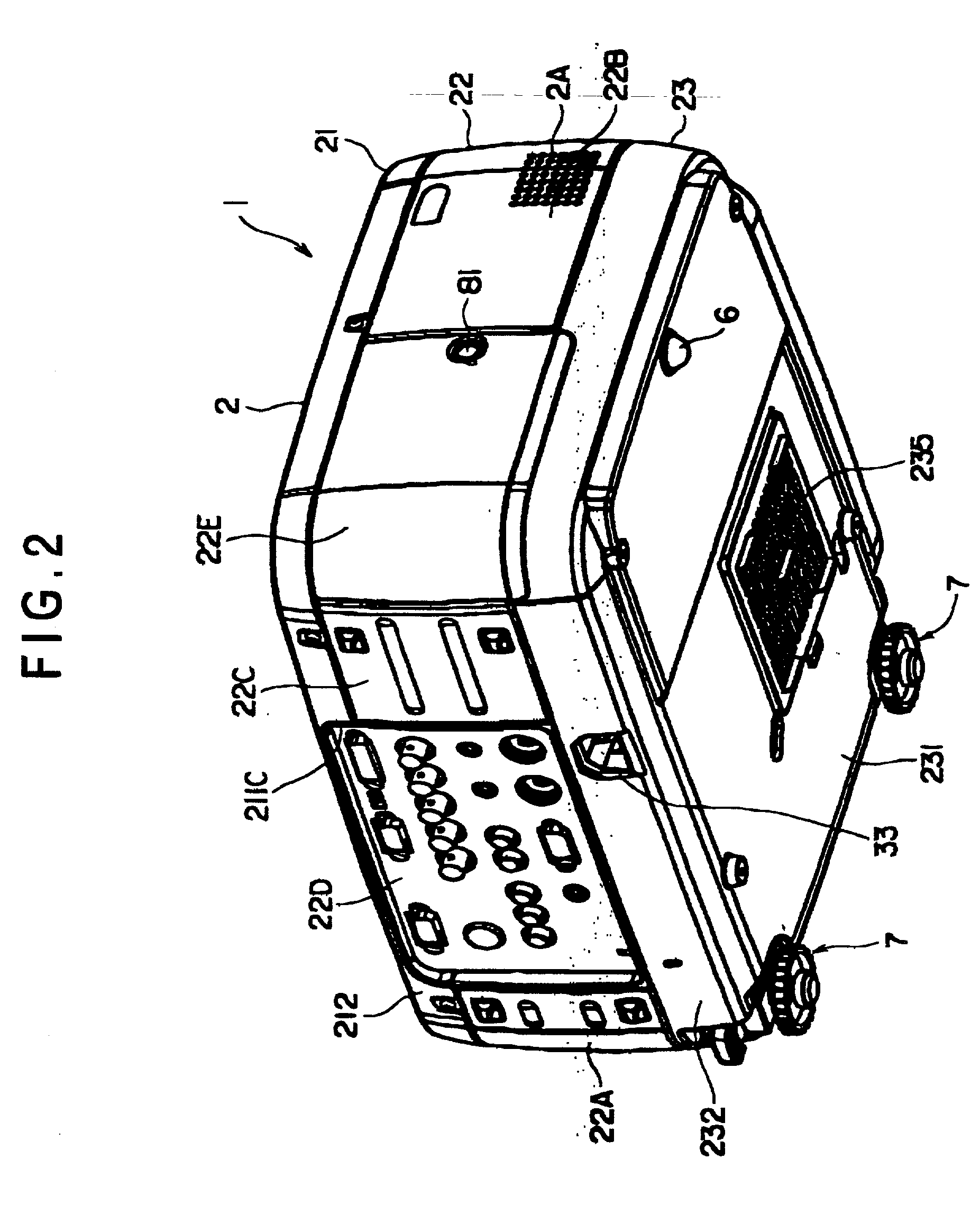
[0061] FIG. 1 is an entire perspective view seen from above showing a projector 1 according to the present embodiment, FIG. 2 is another entire perspective view seen from below showing the projector 1 and FIG. 3 is a perspective view showing interior arrangement of the projector 1.

[0062] The projector 1 separates a light beam irradiated from a light source into three primary colors of red (R), green (G) and blue (B), modulates the light beams of respective colors in accordance with image information through the liquid crystal panel as an optical modulator constituting an electric optical device and combines the modulated light beams of respective colors by a cross dichroic prism to enlarge and display the beam on a projecting surface through a projection lens 46. Though respective components are accommodated in an exterior case 2, the...


PUM

PropertyMeasurementUnit
aspect ratioaaaaaaaaaa
areaaaaaaaaaaa
colorsaaaaaaaaaa

Abstract

A support member (311) for supporting liquid crystal panels (441R, 441G, 441B) is disposed parallel to a cooling air flow channel formed between a light-incident end of a cross dichroic prism (45) and the respective liquid crystal panels and is constructed by a pair of components for supporting a neighborhood of the ends of the respective liquid crystal panels, so that the gap between the light-incident end of the cross dichroic prism and the respective liquid crystal panels facing the cooling air flow channel can be enlarged, thereby flowing cooling air sufficient for cooling a polarizer (446) and the respective liquid crystal panels in a direction of the cooling air flow channel for efficiently cooling them.

Description

[0001] 1. Field of the Invention[0002] The present invention relates to a cooling mechanism of an optical modulator attached to a light-incident end of a prism, an optical modulator attachment unit for attaching the optical modulator on a light-incident end of the prism and a projector having the same.[0003] 2. Description of Related Art[0004] Conventionally, a projector including three optical modulators for modulating a plurality of colors of light in accordance with image information, a cross dichroic prism for combining the color light modulated by the three optical modulator, and a projection lens for enlarging and projecting the light combined by the prism has been used.[0005] Such projectors have been widely used for multimedia presentation in a meeting, scientific society, exhibition etc., and size reduction thereof has been strongly desired since such projectors are brought to other locations as necessary and is brought to other places for storing.[0006] In recent years, in...

Claims


Application Information

Patent Timeline
Patent Type & Authority Applications(United States)
IPC IPC(8): G02F1/13G02F1/133G02F1/1335G02F1/13357G03B21/00G03B21/16H04N9/31
CPCG02F1/133385H04N9/3105H04N9/3144H04N9/3197G03B21/16
Inventor WATANABE, NOBUO
Owner SEIKO EPSON CORP
Why Eureka
Try Eureka