
Pre-terminated optical fibre cable assembly, methods of manufacture and installation thereof

Active Publication Date: 2020-01-09
EMTELLE UK
View PDF0 Cites 5 Cited by
  • Summary
  • Abstract
  • Description
  • Claims
  • Application Information

AI Technical Summary

Benefits of technology

[0061]The method of installing a pre-terminated construction, may further comprise clamping the protective sleeve proximate the duct exit, wherein clamping the protective sleeve is effective to prevent movement of the optical fibre relative to the duct.
[0062]The s

Problems solved by technology

It will be appreciated that fitting a manufactured length of the woven or braided tube pre-fitted with collars/connectors can be problematic.
The transmission line cannot be pulled back, if it has been installed by blowing, and it cannot be trimmed without losing the benefits of pre-termination
However, trimming the sheath and securing the sheath to the ferrule end and duct end of the sheath can be time consuming and risks local damage to the transmission line during the process

Method used


Image

  • Pre-terminated optical fibre cable assembly, methods of manufacture and installation thereof
  • Pre-terminated optical fibre cable assembly, methods of manufacture and installation thereof
  • Pre-terminated optical fibre cable assembly, methods of manufacture and installation thereof

Examples


Example

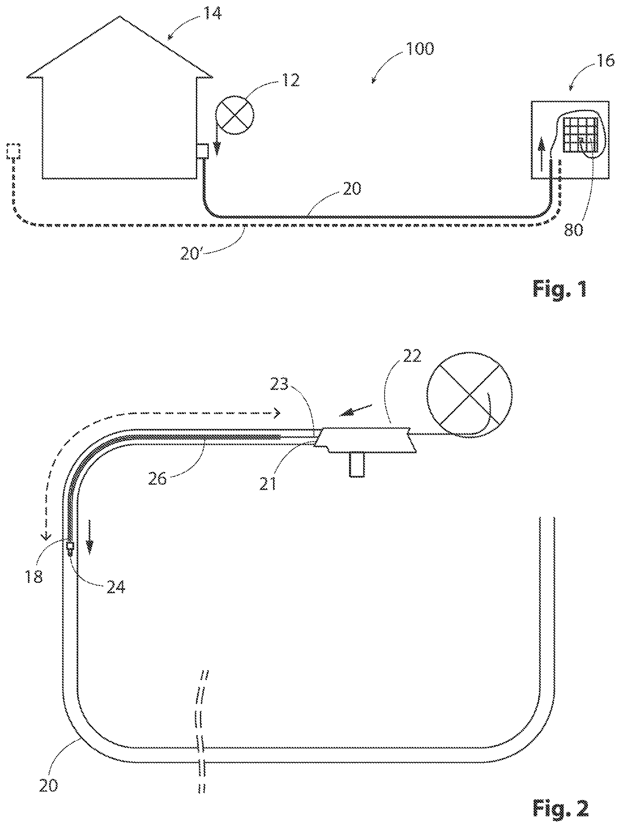
[0078]FIGS. 1 and 2 show an example of a Fibre to the Home (FTTH) installation 100 of optical fibres, using a pre-terminated optical fibre cable assembly 10 according to an embodiment of the present invention. It will be understood that terms such as “consumer” and “home” are used by way of example only, and the products and techniques described herein may equally be applied in commercial and industrial installations.

[0079]In the illustrated example, the pre-terminated cable assembly 10 is provided wound on a reel 12 from which pre-terminated optical fibre or fibres are delivered from the consumer side / home side 14 of the installation 100 to the supply side, for example a telecommunications cabinet 16. Instead of a reel 12, the pre-terminated cable assembly 10 may be provided in other forms, for example in a coil, in a fibre pan etc.

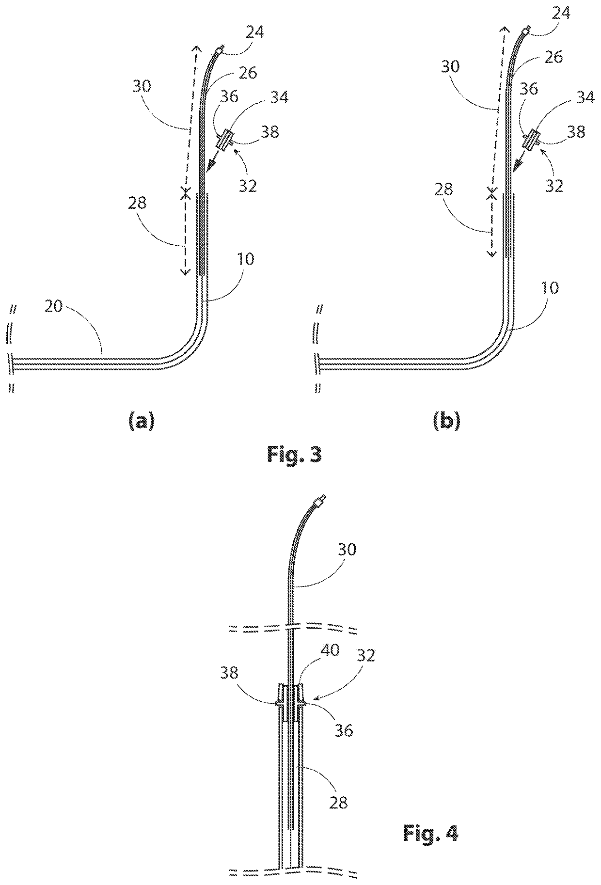
[0080]Referring also to FIG. 2, in the illustrated example, the FTTH installation 100 is performed by passing it into a pre-installed duct 20. Other duc...


PUM


Abstract

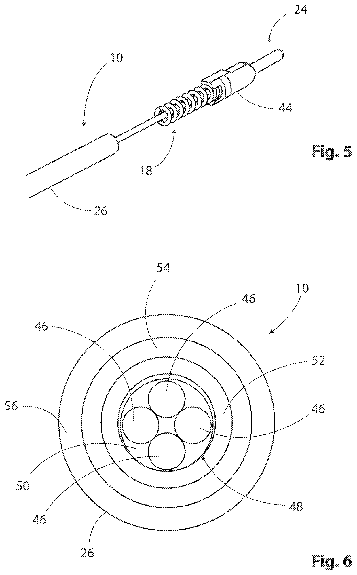
The present invention relates to a pre-terminated (pre-terminated) optical fibre cable assembly (10,90), which is configured to be installed through a duct (20). The pre-terminated optical fibre construction (10,90) includes at least one optical fibre (46). A protective sleeve (26) is added to the optical fibre (46) before adding a terminal connector (24) to the leading end of at least one optical fibre (46). The protective sleeve (26) extends from behind the terminal connector (24) along part of the length of the optical fibre (46). When the cable is installed through a duct, the protective sleeve protects the portion of the fibre that protrudes from the end of the duct, for example in a communications cabinet (16). A residual length (28) of the protective sleeve remains within the duct. Terminal connectors and protective sleeves can be applied at both ends of the cable assembly, or only one end.

Description

FIELD OF THE INVENTION[0001]The present invention relates to improved pre-terminated (also called “pre-connectorised”) optical fibre cables. The invention further relates to methods of manufacture and installation of pre-terminated optical fibre cables.BACKGROUND TO THE INVENTION[0002]Optical fibre transmission lines can be installed through a duct, for example a so-called micro-duct, using compressed gas or fluid, for example air. This is known as installation by blowing, and special lightweight cable assemblies known as “fibre units” have been developed for this installation method. Optical fibre transmission lines can also be installed by pushing, or pulling, or preinstalled in a duct. Different cable designs can be used for these different methods. For example, a cable adapted for installation by pulling may include strengthening fibres, surrounding the optical fibres with in an outer sheath.[0003]Fibre to the home (FTTH) is the generic term for broadband network architecture th...

Claims


Application Information

Patent Timeline
IPC IPC(8): G02B6/44G02B6/50
CPCG02B6/4471G02B6/4486G02B6/4438G02B6/50G02B6/4432G02B6/3887G02B6/545G02B6/52G02B6/443
Inventor KIRKPATRICK, EBEN COLIN
Owner EMTELLE UK
Learn More