
Data moving method for flash memory module, and memory controller and memory storage apparatus using the same

Active Publication Date: 2013-03-07
PHISON ELECTRONICS
View PDF8 Cites 5 Cited by
  • Summary
  • Abstract
  • Description
  • Claims
  • Application Information

AI Technical Summary

Benefits of technology

The present invention relates to a method, controller, and storage apparatus for efficiently moving page data in a flash memory module into one physical page. This improves data access speed and reduces the time required for data movement. The technical effect is greater efficiency in data movement.

Problems solved by technology

Furthermore, citation or identification of any document in this application is not an admission that such document is available as prior art to the invention, or that any reference forms a part of the common general knowledge in the art.

Method used


Image

  • Data moving method for flash memory module, and memory controller and memory storage apparatus using the same
  • Data moving method for flash memory module, and memory controller and memory storage apparatus using the same
  • Data moving method for flash memory module, and memory controller and memory storage apparatus using the same

Examples


first exemplary embodiment

[0039]A memory storage apparatus (i.e., a memory storage system) typically includes a flash memory module and a controller (i.e., a control circuit). The memory storage apparatus is usually used together with a host system, such that the host system can write data into or read data from the memory storage apparatus.

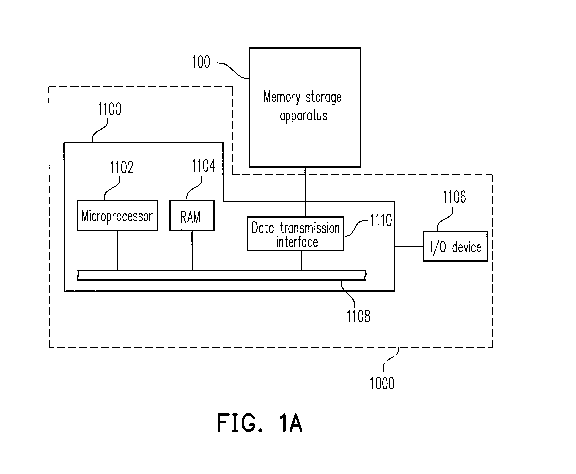
[0040]FIG. 1A illustrates a host system and a memory storage apparatus according to a first exemplary embodiment of the present invention.

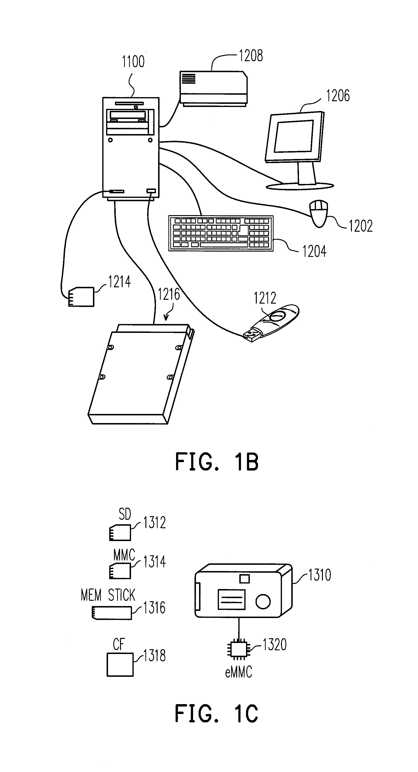
[0041]With reference to FIG. 1A, a host system 1000 includes a computer 1100 and an input / output (I / O) device 1106. The computer 1100 includes a microprocessor 1102, a random access memory (RAM) 1104, a system bus 1108, and a data transmission interface 1110. The I / O device 1106 includes a mouse 1202, a keyboard 1204, a display 1206, and a printer 1208 as shown in FIG. 1B. It should be understood that the I / O device 1106 is not limited to the devices illustrated in FIG. 1B and may further include other devices.

[0042]In the exemplary emb...

second exemplary embodiment

[0108]The second exemplary embodiment is substantially the same as the first exemplary embodiment, while the difference therebetween lies in that the memory management circuit 202 in the second exemplary embodiment can further perform an error correcting operation on the moved data. The drawings utilized to elaborate the first exemplary embodiment will further serve as references to describe the difference between the first exemplary embodiment and the second exemplary embodiment.

[0109]FIGS. 17˜19 schematically illustrate that a valid page data belonging to a logical page is moved from physical pages to a blank physical page according to a second exemplary embodiment of the present invention. It is assumed that the valid data at addresses of the preceding 4 KB of data in the logical page LL0 (hereinafter referred to as the first portion of data) is stored at the preceding 4 KB of addresses in the physical page PP1, and the valid data at the succeeding 4 KB of addresses in the logica...


PUM


Abstract

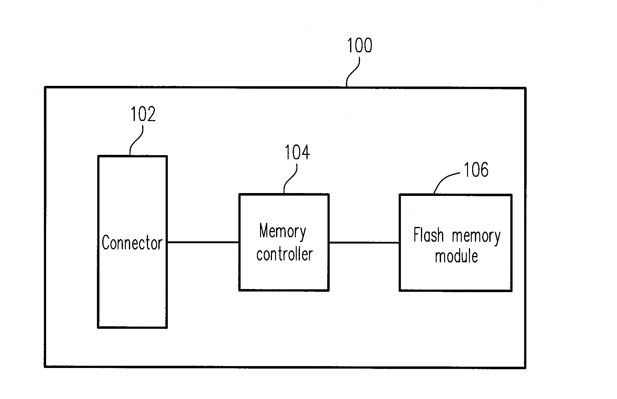
A method of moving a first portion of data and a second portion of data, which belong to one page data and respectively stored in a second physical page and a third physical page, into a first physical page in a flash memory module is provided. The method includes transmitting a read command for reading page data stored in the second physical page; reading the first portion of data from a buffer area of the rewritable non-volatile memory module into a buffer memory; transmitting a read command for reading page data stored in the third physical page; transmitting the first portion of data from the buffer memory to the buffer area; and transmitting a write command for writing data stored in the buffer area into the first physical page. Accordingly, the method can effectively move one page data dispersedly stored in different physical pages into one physical page.

Description

CROSS-REFERENCE TO RELATED APPLICATION[0001]This application claims the priority benefit of Taiwan application serial no. 100132133, filed on Sep. 6, 2011. The entirety of the above-mentioned patent application is hereby incorporated by reference herein and made a part of this specification.BACKGROUND[0002]1. Technology Field[0003]The present invention relates to a data moving method for a flash memory module, a memory controller using the method, and a memory storage apparatus using the method.[0004]2. Description of Related Art[0005]Digital cameras, mobile phones, and MP3 music players have undergone rapid growth in recent years, so that consumer demand for storage media has also drastically increased. Since a rewritable non-volatile memory has the characteristics of non-volatility of data, low power consumption, small volume, non-mechanical structure, and fast reading and writing speed, the rewritable non-volatile memory is the most adaptable memory to be applied in a portable el...

Claims


Application Information

Patent Timeline
IPC IPC(8): G06F12/00
CPCG06F12/0246G06F2212/1024G06F2212/1044G06F2212/7203G06F2212/7205
Inventor YEH, CHIH-KANG
Owner PHISON ELECTRONICS
Learn More