Belt drive power unit

a belt drive and power unit technology, applied in the field of vehicles, can solve problems such as leaving a portion of the area uncleared

Inactive Publication Date: 2020-01-16
VENTURE PRODS
View PDF0 Cites 3 Cited by
  • Summary
  • Abstract
  • Description
  • Claims
  • Application Information

AI Technical Summary

Problems solved by technology

This results in the machine have to move through additional passes to clear the same area, or results in leaving a portion of the area un-cleared.
This may be dangerous as most of these areas are roadways and / or sidewalks where people may be injured due to unsafe driving or walking conditions if snow or ice is not adequately removed therefrom.

Method used


Image

  • Belt drive power unit
  • Belt drive power unit
  • Belt drive power unit

Examples


Embodiment Construction

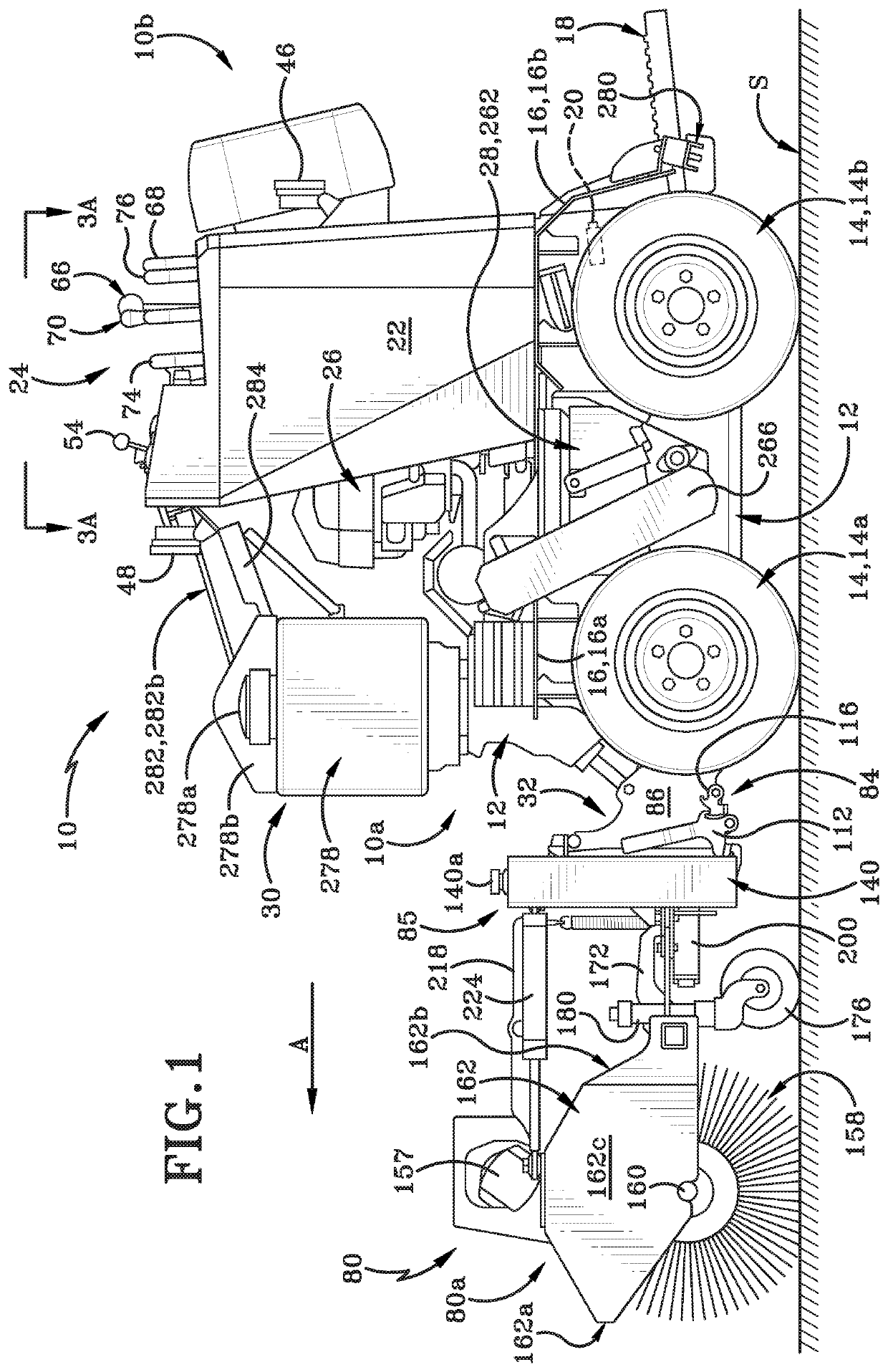
[0059]A power unit in accordance with the present disclosure is illustrated in FIGS. 1-21 and is generally indicated herein by the reference number 10. Power unit 10 is shown and described herein as a powered vehicle that has differential steering. One example of such a powered vehicle is a skid steer-style vehicle that may carry and operate various attachments and implements. Examples of suitable skid steer style vehicles that may be used as power unit 10 are those sold under the name BOBCAT® by The Bobcat Company of North Dakota, USA or those sold under the name JOHN DEERE® by Deere & Company of Illinois, USA.

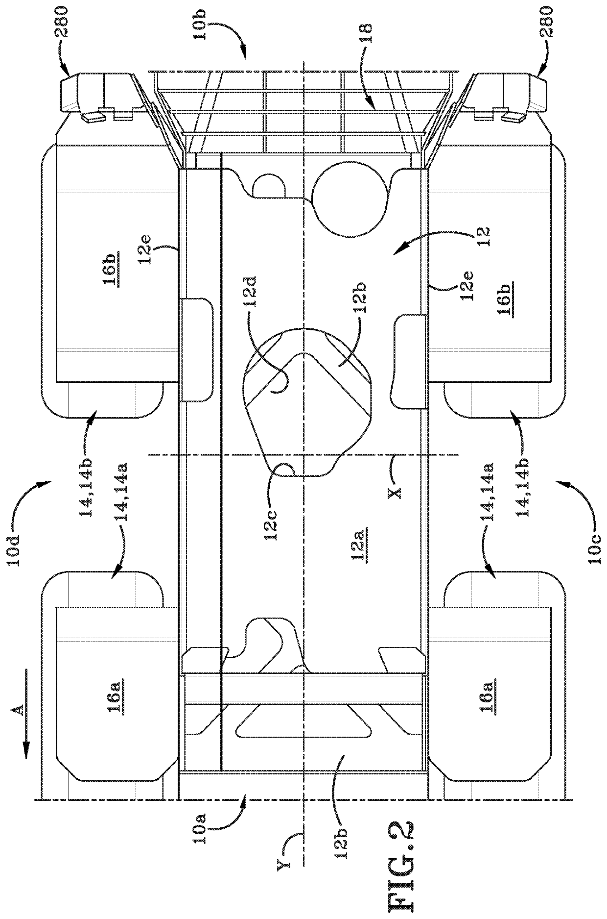
[0060]Power unit 10 has a front 10a and a rear 10b defining a longitudinal direction therebetween. Power unit 10 further includes a left side 10c (FIG. 2) and a right side 10d defining a transverse direction therebetween. Power unit 10 includes a longitudinal axis “Y” (FIG. 2) extending between front 10a and rear 10b and a traverse axis “X” extending between left side 10c and...


PUM


Abstract

Skid-steer type power unit engageable with an implement using an attachment assembly including an attachment frame and a hitch. An arcuate frame member is located forwardly of the attachment frame and is engaged therewith in such a way that the frame member pivots about a vertical axis located forwardly of the frame member and generally centrally positioned relative to the attachment frame. The frame member pivots in response to actuation of a hydraulic cylinder. The power unit includes a system for transferring weight of the implement rearwardly onto the power unit. A belt-drive power-take off system on the power unit powers the implement's operation. An underbelly drop spreader is located between the front and rear wheels of the power unit and a brine delivery system distributes brine from nozzles located rearwardly of the rear wheels. A unique control panel permits operation of all systems on the power unit and implement.

Description

CROSS-REFERENCE TO RELATED APPLICATION[0001]This application claims the benefit of U.S. Provisional Application Ser. No. 62 / 696,161, filed Jul. 10, 2018, the disclosure of which is incorporated herein by reference.BACKGROUNDTechnical Field[0002]The present disclosure generally relates to vehicles. More particularly, the present disclosure is directed to a skid steer style vehicle having one or more implements mounted thereon. Specifically, the present disclosure relates to a vehicle with a belt-drive power transfer system, that includes a novel attachment assembly for at least one snow and / or ice removal implement, and that has a novel control system.Background Information[0003]A large number of snow removal devices are currently on the market. These removal devices range from hand-held shovels, through to small household-sized snowblowers, and on to large snowplows and salting and sanding vehicles used to clear city streets and large areas such as airport runways.[0004]There exists...

Claims


Application Information

Patent Timeline
Patent Type & Authority Applications(United States)
IPC IPC(8): B60K17/28B60K25/02E01H5/09
CPCB60K2025/022E01H5/098B60K17/28B60K25/02E01H3/02E01H5/045E01H5/092E01H10/007E01C19/20A01B59/062E02F3/3663E02F3/3672
Inventor LEHMAN, ROSCOE J.NOLT, CHRISTOPHER A.STEINER, ROY I.
Owner VENTURE PRODS
Why Eureka
Try Eureka