Vapor chamber structure

Active Publication Date: 2020-01-16
ASIA VITAL COMPONENTS SHENZHEN CO LTD
View PDF16 Cites 5 Cited by
  • Summary
  • Abstract
  • Description
  • Claims
  • Application Information

AI Technical Summary

Benefits of technology

The present invention provides a vapor chamber structure that has both large-area heat spreading and remote end heat conduction effects, which results in enhanced heat dissipation performance without the occurrence of thermal resistance.

Problems solved by technology

This will deteriorate the heat conduction efficiency.

Method used


Image

  • Vapor chamber structure
  • Vapor chamber structure
  • Vapor chamber structure

Examples


second embodiment

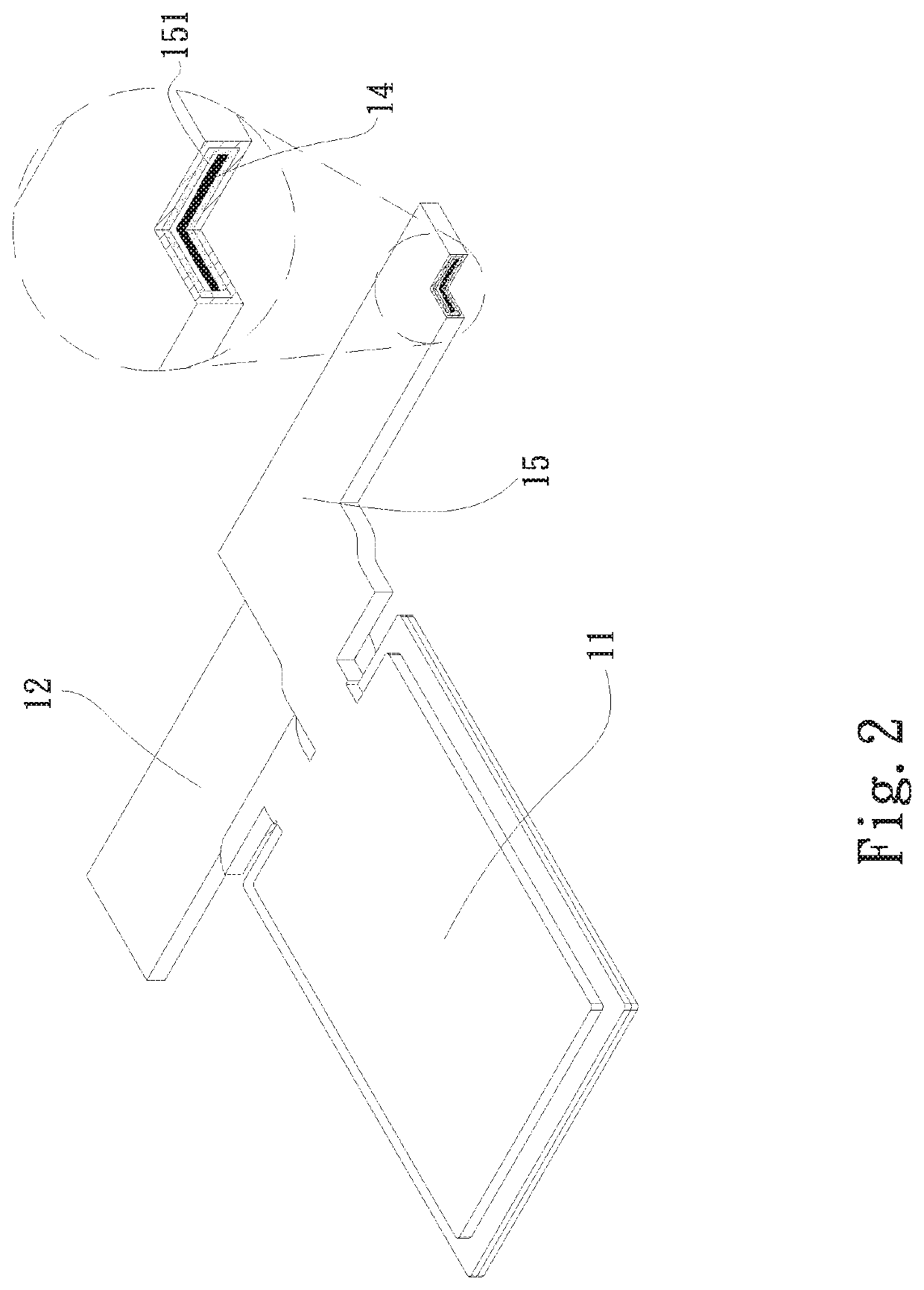
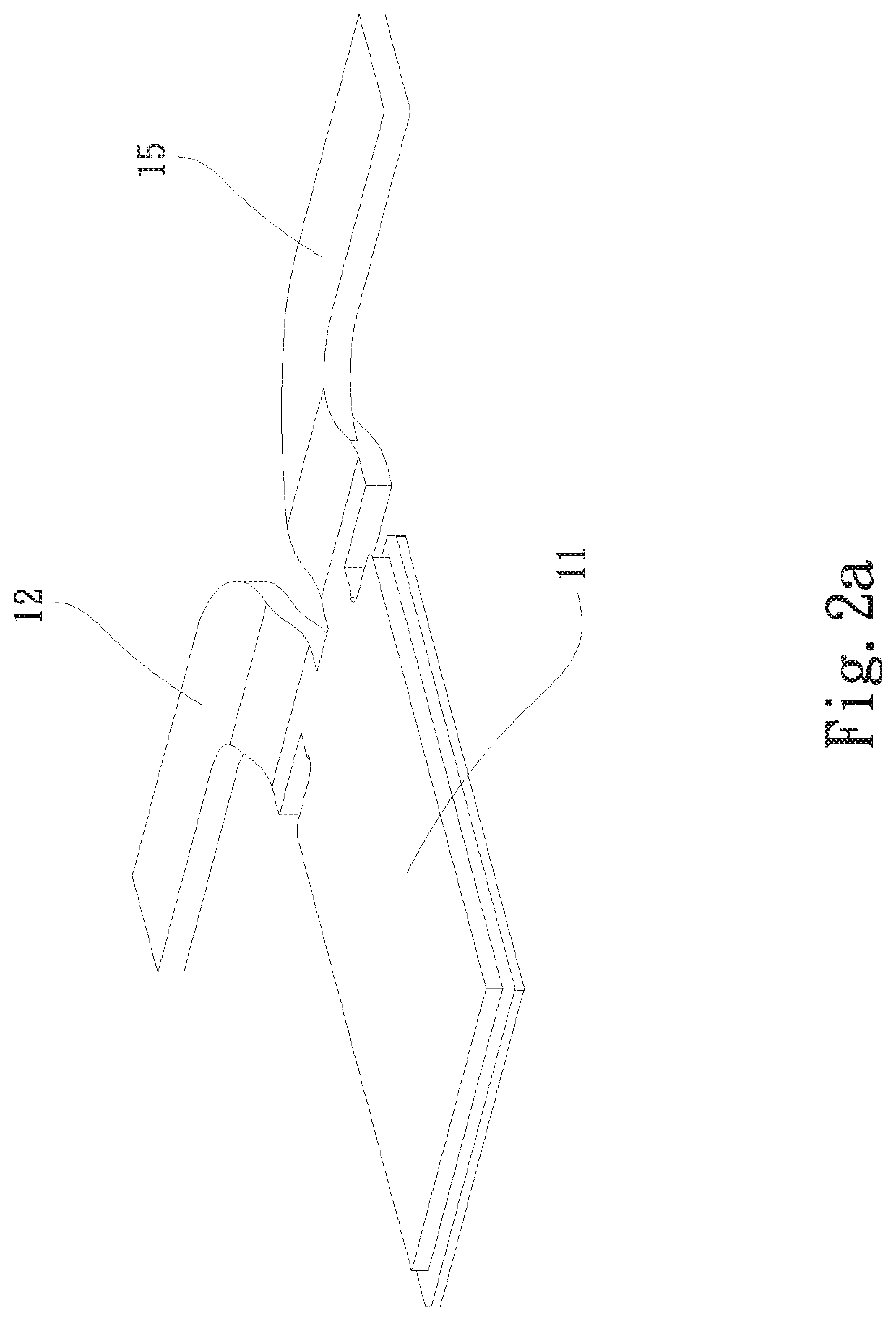
[0024]FIG. 2a shows another aspect of the As shown in the drawing, the second and third sections 12, 15 are positioned on the same level, while the first section 11 is positioned on a different level. In addition, after outward extending from the first section 11, the second and third sections 12, 15 respectively extend to the left and right sides or upper and lower sides of the first section 11.

[0025]Please now refer to FIG. 3, which is a perspective sectional view of a third embodiment of the vapor chamber structure of the present invention. The third embodiment is partially identical to the first embodiment in structure and thus will not be redundantly described hereinafter. The third embodiment is different from the second embodiment in that the second section 12 is connected with a fourth section 16. The fourth section 16 has the form of an elongated plate and is perpendicularly connected with the second section 12 and extends to left and right sides of the second section 12. ...

fourth embodiment

[0027]FIG. 4a shows another aspect of the As shown in the drawing, the fourth section 16 is divided along the central section into two parts. One of the two parts of the fourth section 16 is connected with the sixth section 18, while the other of the two parts of the fourth section 16 is connected with the second section 12. That is, in this aspect, the two parts of the fourth section 16 are respectively independently connected with the second and sixth sections 12, 18.

[0028]A portion of the fourth section 16 near a rear end thereof is perpendicularly bent to extend. Multiple radiating fins 2 are fitted on the extending portion of the fourth section 16. In this embodiment, the fourth section 16 and the fifth section 17 have a height difference. The position and height of the height difference can be freely adjusted by a designer in accordance with the space to be designed and the corresponding heat source in adaptation to the space. In this embodiment, multiple radiating fins 2 are...


PUM


Abstract

A vapor chamber structure includes a main body. The main body has a first section, a second section, a capillary structure and a working fluid. The first section has a first chamber. The second section has a second chamber. The second section extends from one end of the first section in a direction away from the first section. The capillary structure is disposed on inner surfaces of the first and second chambers. The working fluid is filled in the first and second chambers. The vapor chamber structure has both heat spreading effect and remote end heat dissipation effect.

Description

BACKGROUND OF THE INVENTION1. Field of the Invention[0001]The present invention relates generally to a vapor chamber structure, and more particularly to a vapor chamber structure having both face-to-face heat spreading effect and remote end heat dissipation effect.2. Description of the Related Art[0002]Currently, the most often used heat dissipation components include heat sinks, heat pipes, heat plates, vapor chambers, etc., wherein the heat sinks mainly serve to help in dissipating the heat, while the heat pipes, heat plates and vapor chambers are able to quickly conduct heat and thus serve as heat conduction components. The heat conduction components have high heat conduction coefficient so that they can serve as the main components in direct contact with the heat source. The heat conduction components can be additionally connected with the heat sinks with better heat dissipation effect so as to enhance the heat dissipation efficiency.[0003]As aforesaid, the vapor chamber and the...

Claims


Application Information

Patent Timeline
IPC IPC(8): F28D15/02F28D15/04
CPCF28D15/0266F28D15/0233F28D15/04F28D15/0275
Inventor LIN, SHENG-HUANG
Owner ASIA VITAL COMPONENTS SHENZHEN CO LTD
Why Eureka
Try Eureka