Connector

Pending Publication Date: 2022-05-26
YAZAKI CORP
View PDF0 Cites 2 Cited by
  • Summary
  • Abstract
  • Description
  • Claims
  • Application Information

AI Technical Summary

Benefits of technology

The present invention is aimed at providing a connector that can prevent overheating by improving its heat dissipation performance.

Problems solved by technology

However, these measures are not necessarily preferable because the size of the connector is significantly increased.

Method used


Image

  • Connector
  • Connector
  • Connector

Examples


embodiments

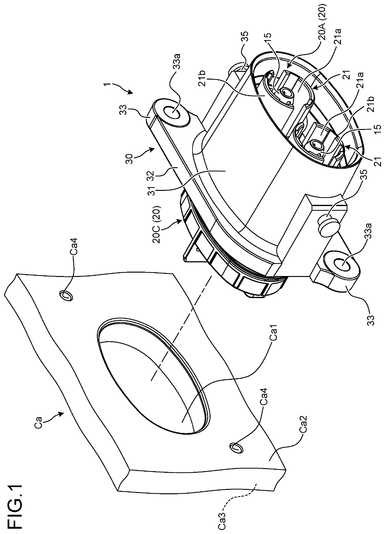
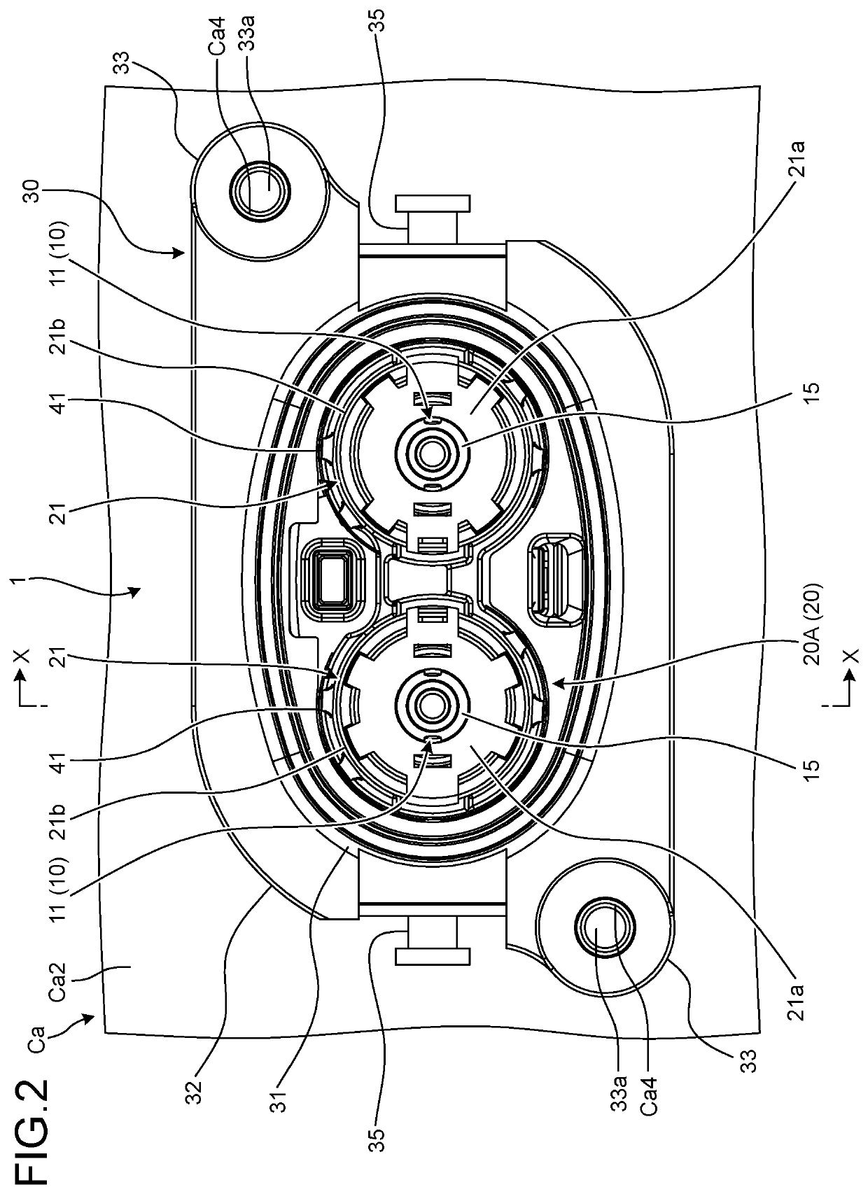
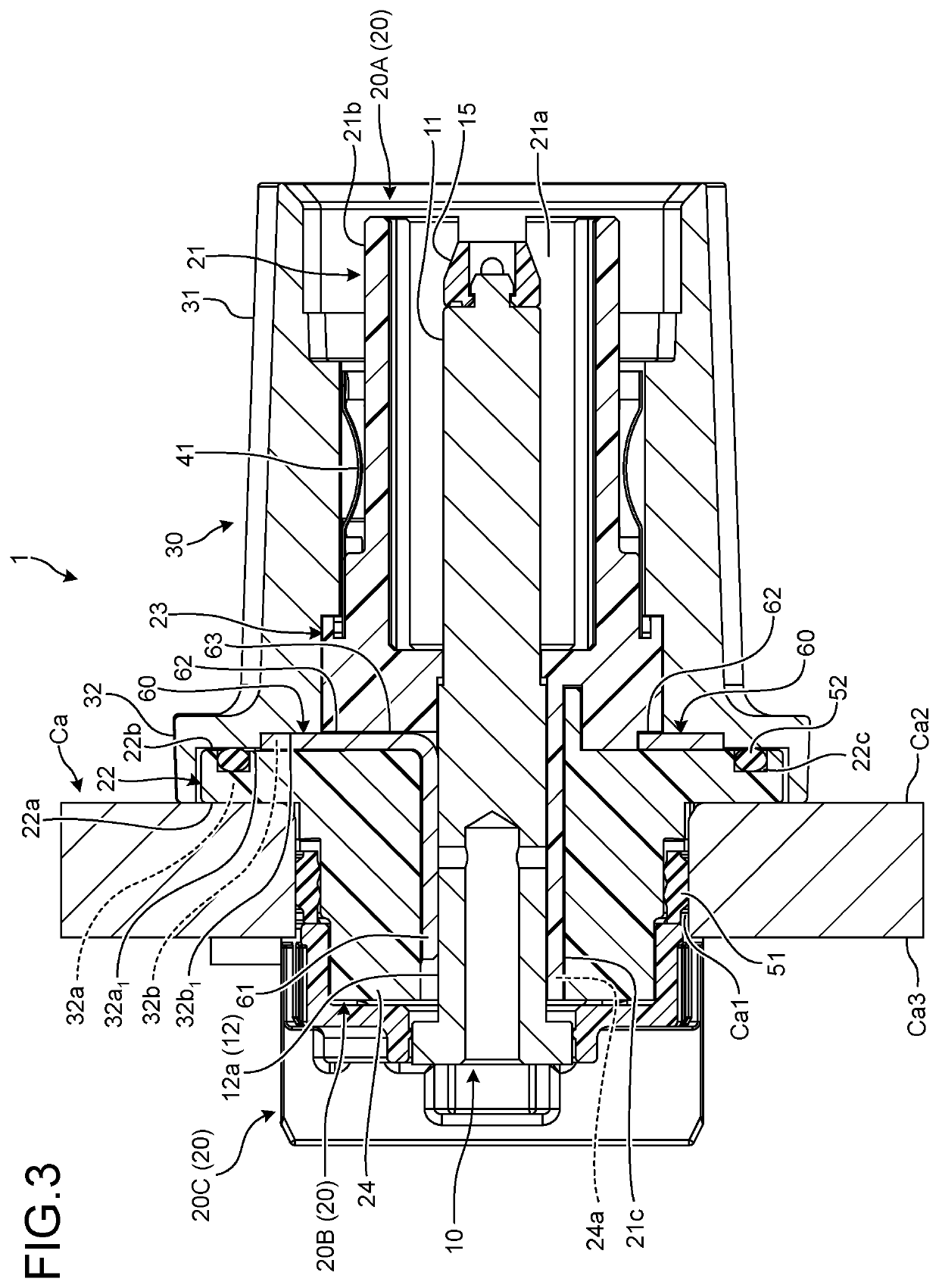
[0025]One of the embodiments of a connector according to the present invention will be described with reference to FIGS. 1 to 10.

[0026]Reference numeral 1 in FIGS. 1 to 7 denotes a connector according to the present embodiment. The connector 1 is attached to a metal casing Ca (FIGS. 1 to 3) of an installation target device, and with a counterpart connector 501 (FIGS. 8 to 10) fitted and connected, electrically connect the installation target device and a device (not illustrated) ahead of the counterpart connector 501. For example, the connector 1 electrically connects a battery as an installation target device mounted on the vehicle and an inverter as a device, ahead of the counterpart connector 501, mounted on the vehicle.

[0027]The connector 1 includes a terminal fitting 10, a housing 20, and a shield shell 30 (FIGS. 2 and 4).

[0028]The terminal fitting 10 is formed of a conductive material such as metal. The terminal fitting 10 is physically and electrically connected to a counterp...


PUM


Abstract

A connector includes a terminal fitting, an insulating housing having a terminal accommodation chamber in which the terminal fitting is accommodated, and attached to a casing of an installation target device, and an insulating heat dissipation member that takes heat from the terminal fitting and dissipates the heat are included, and the heat dissipation member includes a heat absorbing portion that comes into contact with the terminal fitting in the terminal accommodation chamber and takes heat from the terminal fitting, and a heat transfer portion that transfers the heat taken by the heat absorbing portion to a heat transfer target portion outside the terminal accommodation chamber.

Description

CROSS-REFERENCE TO RELATED APPLICATION(S)[0001]The present application claims priority to and incorporates by reference the entire contents of Japanese Patent Application No. 2020-194778 filed in Japan on Nov. 25, 2020.BACKGROUND OF THE INVENTION1. Field of the Invention[0002]The present invention relates to a connector.2. Description of the Related Art[0003]In the related art, the connector is connected to the counterpart connector so that the terminal fittings can be in an energized state. This type of connector is disclosed in, for example, Japanese Patent Application Laid-open No. 2011-204610.[0004]In the connector, the amount of heat generated at the terminal fitting or the electric wire increases as the current of the device to which the connector is connected increases. Therefore, in the conventional connector, an increase in temperature is suppressed by increasing the size of the terminal fitting, increasing the wire diameter of the electric wire, or the like. However, these...

Claims


Application Information

Patent Timeline
IPC IPC(8): H01R24/66
CPCH01R24/66H01R13/5202H01R2201/26H01R13/533H05K7/2039H01R2103/00H01R13/748H01R13/6591H01R13/6583H01R13/62938
Inventor UKI, KAZUTAKA
Owner YAZAKI CORP
Why Eureka
Try Eureka