Speaker

Active Publication Date: 2013-10-17
ALPINE ELECTRONICS INC
View PDF4 Cites 16 Cited by
  • Summary
  • Abstract
  • Description
  • Claims
  • Application Information

AI Technical Summary

Benefits of technology

[0010]The metal partition wall separates the outer space in a high-temperature environment, in which the case of the speaker is installed, from the acoustic space, into which the sound port of the duct of the speaker faces and protrudes. Because the metal partition wall has a large thermal capacity, the metal partition wall can function as a heatsink. By focusing on this point and configuring the speaker such that the thermal conductive sheet is sandwiched between the partition wall and the end surface of the magnetic circuit adjacent to the partition wall, heat generated by the voice coil disposed in the case and heat that accumulates in the magnetic circuit can be efficiently dissipated to the partition wall through the thermal conductive sheet. Therefore, even when the outer space in which the speaker is installed is a high-temperature environment such as an engine compartment, an increase in the temperatures of the voice coil and the magnetic circuit can be suppressed, and, as a result, a good speaker performance can be maintained. In a neodymium magnet of a magnetic circuit used in a high-temperature environment, dysprosium (Dy) is usually included in order to increase the heat resistance of the magnet. The amount of dysprosium, which is an expensive material, can be reduced by configuring the speaker so that an increase in the temperature of the magnetic circuit can be suppressed even in a high-temperature environment. As a result, the cost of the speaker can be reduced.
[0011]In the speaker described above, it is preferable that the thermal conductive sheet is a silicone-based thermal conductive sheet, which has high heat conductivity and which is frame-retardant. It is preferable that a part of the magnetic circuit be inserted into the heat dissipation port of the case. In this case, the speaker can be easily manufactured, beca

Problems solved by technology

However, it may be difficult to form a large opening in a wall of a vehicle cabin so as to face the diaphragm of a speaker.
However, when a speaker is installed in a high-temperature environment such as an engine comp

Method used


Image

  • Speaker
  • Speaker
  • Speaker

Examples


Example

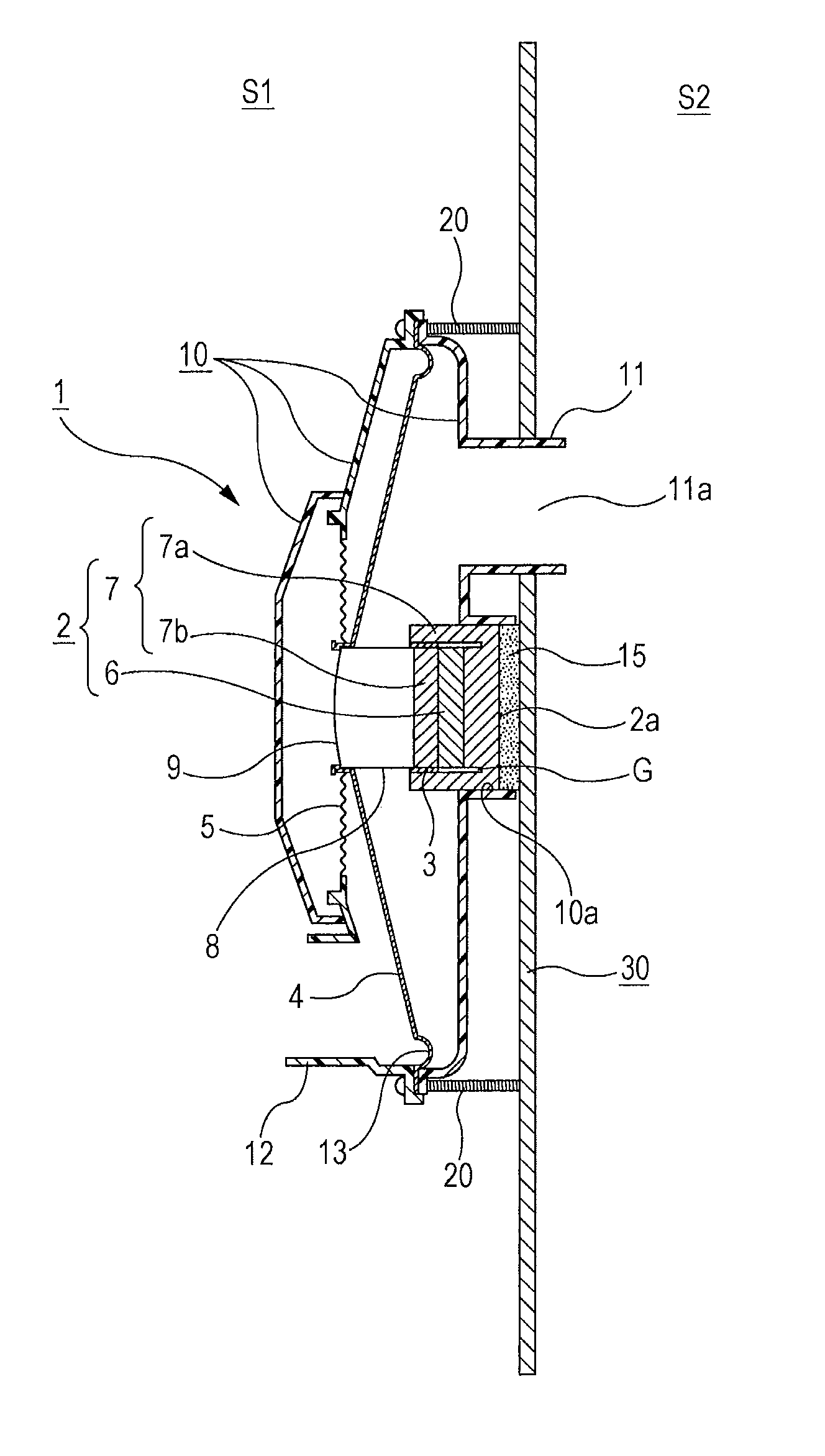
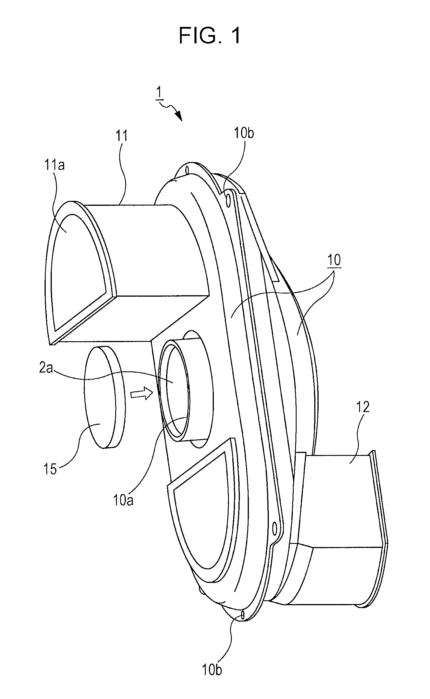
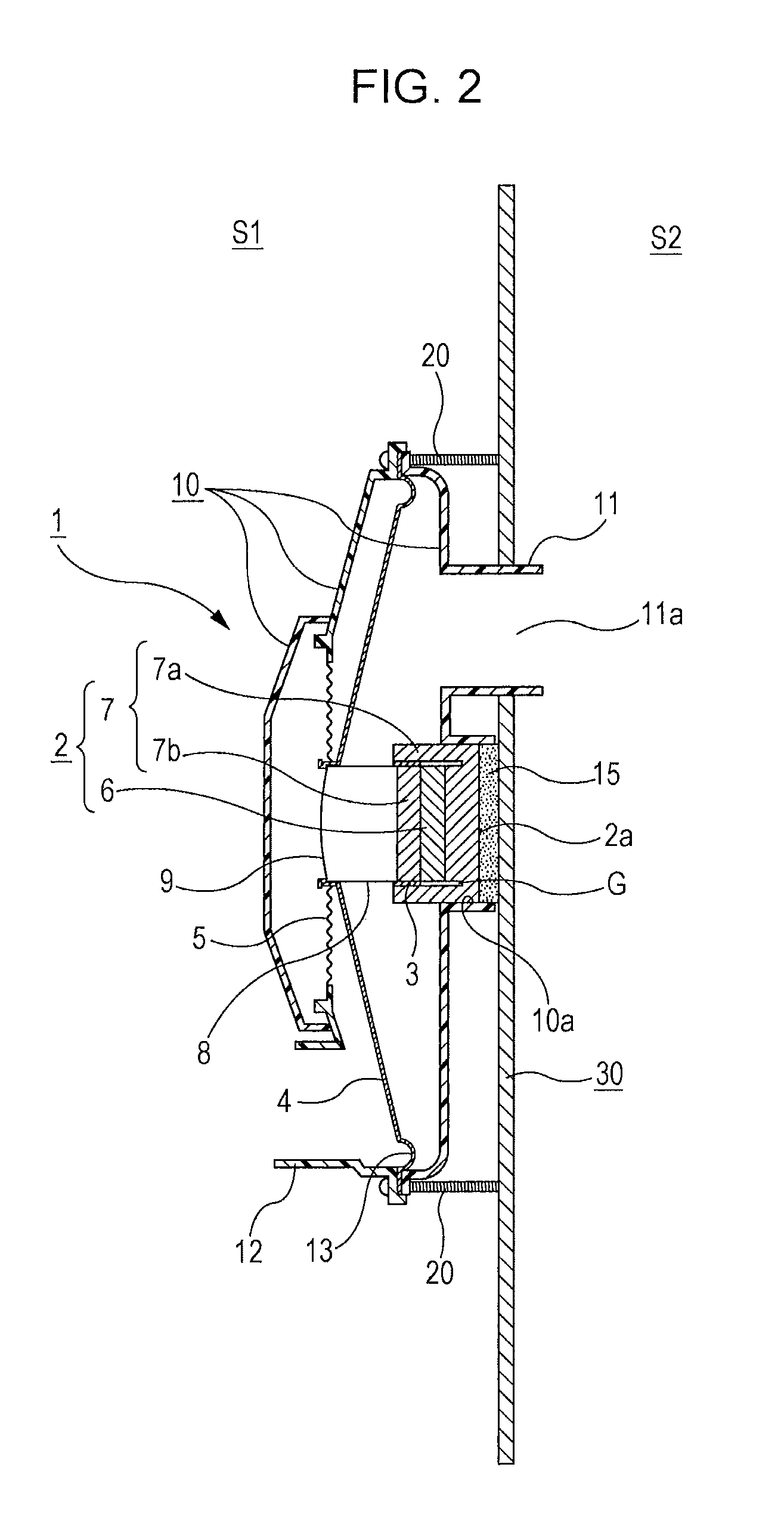
[0017]Hereinafter, an exemplary embodiment of the present invention will be described with reference to the drawings. A speaker 1 according to the exemplary embodiment of the present invention is a car subwoofer. As illustrated in FIG. 2, the speaker 1 is installed in an engine compartment S1 of an automobile, and reproduced sound generated by the speaker 1 is emitted to a cabin space S2. A partition wall 30, which is a vehicle body frame made of a metal, is present between the engine compartment S1 and the cabin space S2. A hole 31 (see FIG. 4) is formed in the partition wall 30; and a duct 11, which protrudes outward from a case 10 of the speaker 1, is inserted into the hole 31. That is, the engine compartment S1 is used as an installation space for installing the speaker 1; a distal open end of the duct 11, which is inserted into the partition wall 30, is a sound port 11a; and the sound port 11a faces and protrudes into the cabin space S2, which is an acoustic space. The cross-se...


PUM

PropertyMeasurementUnit
Elasticityaaaaaaaaaa
Thermal conductivityaaaaaaaaaa

Abstract

A speaker includes a magnetic circuit, a voice coil, and a diaphragm which are disposed in a case. The case is placed in an engine compartment of an automobile. Reproduced sound is emitted through a duct protruding outward from the case. A partition wall, which is a metal body frame of the automobile, is present between the engine compartment and the cabin space. The duct is inserted into a hole formed in the partition wall so that a sound port faces and protrudes into the cabin space. A heat dissipation port is formed in the case, and an end surface the magnetic circuit facing the partition wall is exposed in the heat dissipation port. An elastically deformable thermal conductive sheet is sandwiched between the partition wall and the end surface of the magnetic circuit.

Description

RELATED APPLICATIONS[0001]The present application claims priority to Japanese Patent Application Number 2012-093966, filed Apr. 17, 2012, the entirety of which is hereby incorporated by reference.BACKGROUND[0002]1. Field of the Invention[0003]The present invention relates to an electrodynamic speaker that is preferably used in vehicles or the like, and in particular, to such a speaker that can be installed in a high-temperature environment such as an engine compartment.[0004]2. Description of the Related Art[0005]When a relatively large car speaker for reproducing sounds in a low-frequency range, such as a subwoofer, is installed in a vehicle cabin, the available space in the vehicle cabin is reduced. Therefore, in recent years, a method has been used in which a speaker is disposed in a space outside of a vehicle cabin, and reproduced sound generated by the speaker is emitted to a space inside of the vehicle cabin through an opening formed in a wall of the vehicle cabin. However, it...

Claims


Application Information

Patent Timeline
IPC IPC(8): H04R9/02H04R31/00
CPCH04R9/022H04R31/00H04R2499/13Y10T29/49005
Inventor TADA, ARATAITO, RYO
Owner ALPINE ELECTRONICS INC
Why Eureka
Try Eureka