Inductor element

Active Publication Date: 2015-01-22
MURATA MFG CO LTD
View PDF7 Cites 4 Cited by
  • Summary
  • Abstract
  • Description
  • Claims
  • Application Information

AI Technical Summary

Benefits of technology

The present invention provides an inductor element with improved performance. It achieves this by using a pattern of multiple linear conductors among at least two sheets, with corresponding protrusions formed on the principle surface of the inductor element. This enhances heat dissipation performance. Additionally, the sheets with the common pattern of linear conductors are adjacent to each other in a stacking direction, which connects the linear conductors in parallel. This reduces DC resistance components of the inductor element and improves its operation performance.

Problems solved by technology

However, according to the related art, a resin film is simply wound around a ferrite core, and thus the operation performance of the element is limited.

Method used


Image

  • Inductor element
  • Inductor element
  • Inductor element

Examples


Embodiment Construction

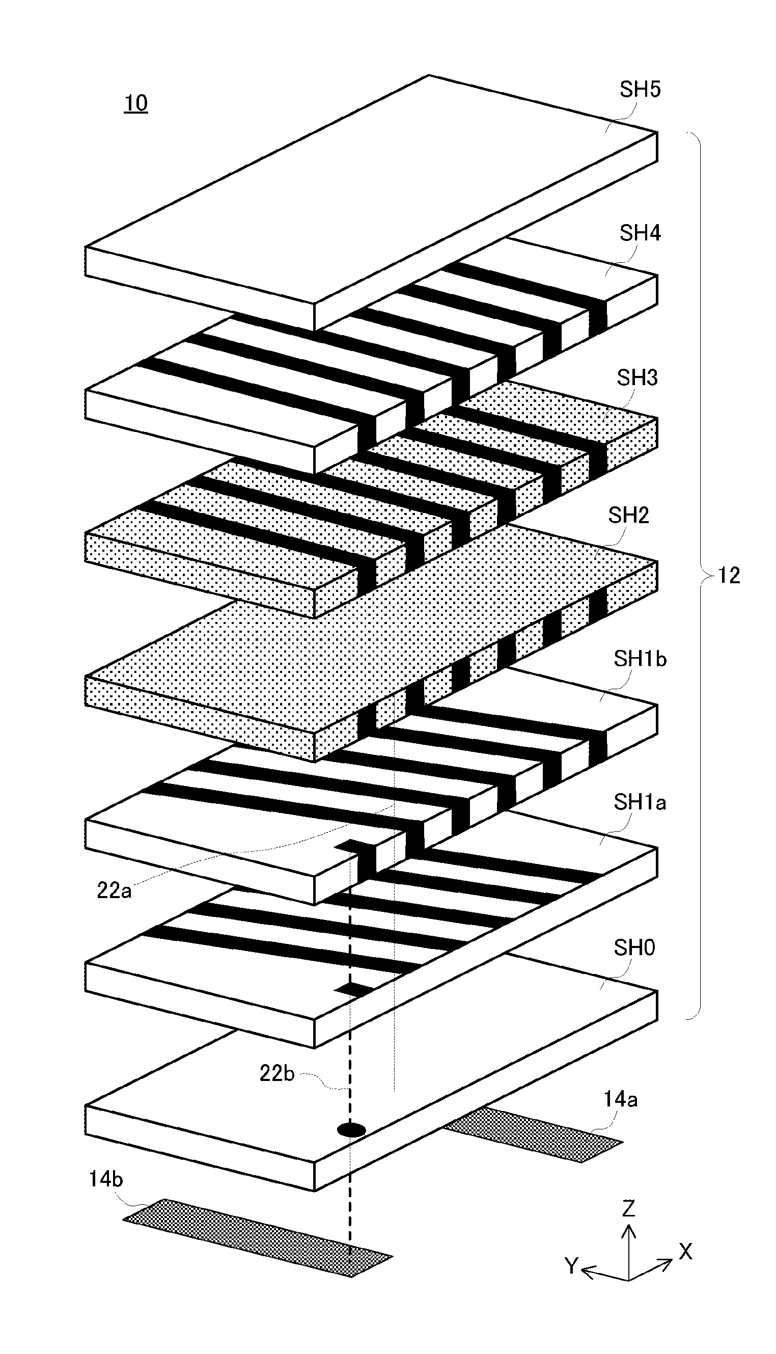
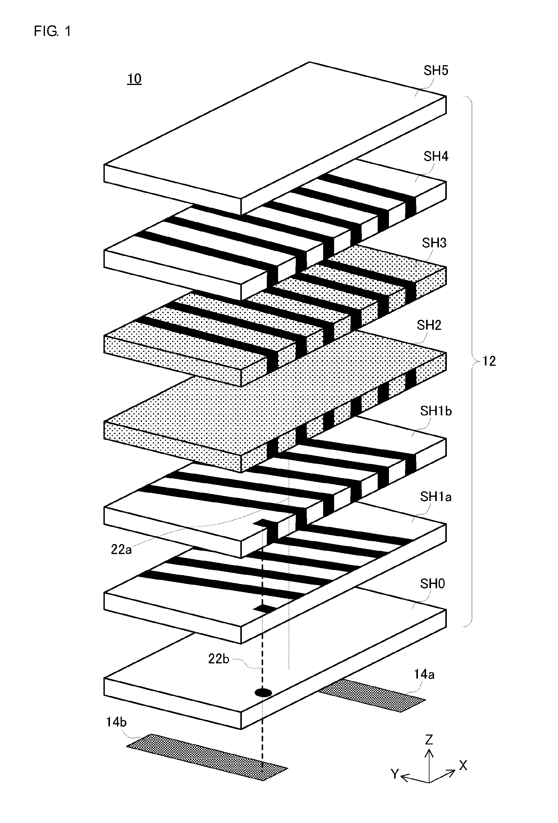
[0029]Referring to FIG. 1, a coil antenna element 10 according to this embodiment includes nonmagnetic sheets SH0, SH1a, SH1b, SH4, and SH5, and magnetic sheets SH2 and SH3, each of which has rectangular principal surfaces. These sheets are stacked in order of “SH0”, “SH1a”, “SH1b”, “SH2”, “SH3”, “SH4”, and “SH5”, and thereby a rectangular parallelepiped multilayer body 12 is fabricated. A long side and a short side of a rectangle that forms a principal surface of the multilayer body 12 extend along an X-axis and a Y-axis, respectively, and a thickness of the multilayer body 12 increases along a Z-axis. A lower surface of the multilayer body 12 is provided with conductor terminals 14a and 14b, which are located at both ends in the X-axis direction.

[0030]The sheets SH0, SH1a, SH1b, and SH2 to SH5 have principal surfaces of the same size. The sheets SH0, SH1a, SH1b, SH4, and SH5 are made of a nonmagnetic ferrite, whereas the sheets SH2 and SH3 are made of a magnetic ferrite. Further, ...


PUM


Abstract

A multilayer body 12 includes nonmagnetic sheets SH1a and SH1b each having an upper surface provided with a plurality of linear conductors 16, a magnetic sheet SH3 having an upper surface provided with a plurality of linear conductors 18a, and a nonmagnetic sheet SH4 having an upper surface provided with a plurality of linear conductors 18b, which are stacked one on top of another. Via-hole conductors or side-surface conductors are disposed with the multilayer body 12 so as to connect these linear conductors to one another and form an inductor. The plurality of linear conductors have a pattern that is common among at least two sheets adjacent to each other in a stacking direction.

Description

BACKGROUND OF THE INVENTION[0001]1. Field of the Invention[0002]The present invention relates to inductor elements, and particularly relates to an inductor element that is applied as an antenna coil for near field communication.[0003]2. Description of the Related Art[0004]An example of this type of element is disclosed in Patent Document 1. According to this related art, an antenna coil includes a magnetic core and a coil that is wound therearound in the longitudinal direction of the magnetic core. The antenna coil is fabricated by winding, around a ferrite core, a resin film that is made of polyimide or the like and has a coil pattern printed thereon.[0005]Patent Document 1: Japanese Unexamined Patent Application Publication No. 2008-35464BRIEF SUMMARY OF THE INVENTION[0006]However, according to the related art, a resin film is simply wound around a ferrite core, and thus the operation performance of the element is limited.[0007]Accordingly, a major object of the present invention ...

Claims


Application Information

Patent Timeline
IPC IPC(8): H01F27/28
CPCH01F2027/2809H01F27/2804H01F5/003H01F17/0033H01F38/14H01Q7/06
Inventor YOKOYAMA, TOMOYASATO, TAKAKO
Owner MURATA MFG CO LTD
Why Eureka
Try Eureka