Microelectromechanical device for out-of-plane motion detection

a micro-electromechanical and out-of-plane technology, applied in the direction of measurement devices, speed/acceleration/shock measurement, instruments, etc., can solve the problems of insufficient difference, insufficient detection area, and insufficient thickness of structure layer in combined design

Active Publication Date: 2020-01-16
MURATA MFG CO LTD
View PDF0 Cites 5 Cited by
  • Summary
  • Abstract
  • Description
  • Claims
  • Application Information

AI Technical Summary

Problems solved by technology

However, structure layer thickness creates challenges in design of combined configurations where in-plane and out-of-plane detection is applied.
This means that areas closer to the rotation axes are not effectively used for detection.
However, for some applications, even this difference

Method used


Image

  • Microelectromechanical device for out-of-plane motion detection
  • Microelectromechanical device for out-of-plane motion detection
  • Microelectromechanical device for out-of-plane motion detection

Examples


Embodiment Construction

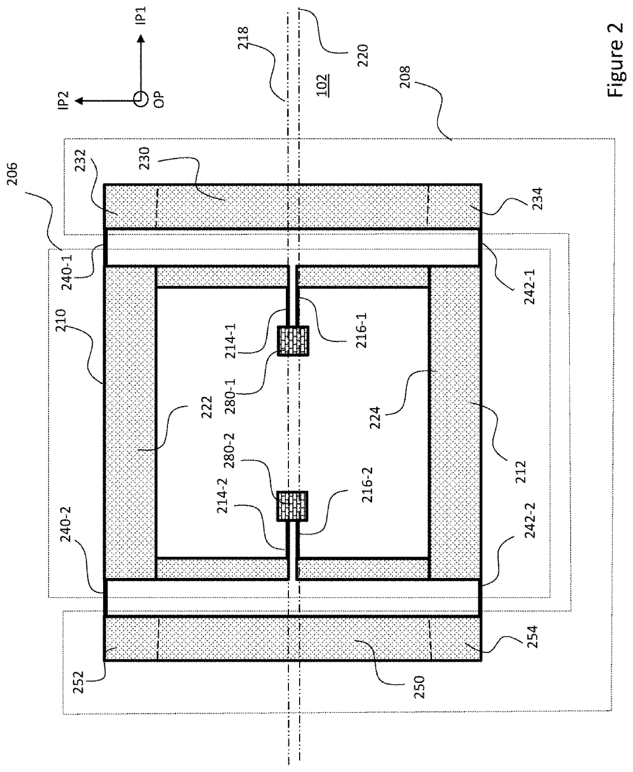
[0027]FIG. 2 shows an example of a novel structure that eliminates, or at least alleviates the above described disadvantages by combining torsional and transversal modes of motion. In the shown example, the device structure 102 includes a rotating mass structure 206 and a linear mass structure 208. The rotating mass structure 206 is formed of two separate rotating mass parts, a first rotating mass part 210 and a second rotating mass part 212. Separate in this context means that each of the two rotating mass parts 210, 212 is elastically coupled to the support 100 through an axial spring structure that is functionally separate from the spring structure of the other rotating mass part. Axial spring structure in this context means that the points of contact to the support and to the rotating mass part are aligned to a spring axis. This means that the center of mass of each of the rotating mass parts can be offset from the spring axis of its axial spring. This provides the necessary lev...


PUM


Abstract

The disclosure relates to a microelectromechanical device where the device structure includes a rotating mass structure and a linear mass structure. The rotating mass structure is formed of two rotating mass parts elastically coupled to the support through one or more springs that enable rotary motion of each of the rotating mass parts about respective rotary axes that extend parallel to each other along a first in-plane direction (IP1). The linear mass structure includes at least one elongate rigid body that extends in a second in-plane direction (IP2). One end of the linear mass structure is coupled to the first rotating mass part and the other end of the linear mass structure is coupled to the second rotating mass part such that rotary motions of the first and second masses result into linear motion of the linear mass structure in the out-of-plane direction (OP).

Description

FIELD OF THE DISCLOSURE[0001]The present disclosure relates to microelectromechanical devices, and more particularly to devices configured for detecting accelerations in out-of-plane direction.BACKGROUND OF THE DISCLOSURE[0002]A microelectromechanical device can be made to move with an object to measure acceleration upon it. For this, the micromechanical device typically includes inertial mass structures, and acceleration forces acting on the micromechanical device can be measured by detecting displacements of these masses relative to fixed electrodes. FIG. 1 shows a side view illustrating basic elements of a microelectromechanical device.[0003]The microelectromechanical device comprises a support 100, and a device structure 102. The term support 100 refers herein to a rigid mechanical element that may be fixed to move with the measured object. Accordingly, the support is a structural element that provides a rigid, locally inert reference for movable elements of the microelectromech...

Claims


Application Information

Patent Timeline
IPC IPC(8): G01P15/125
CPCG01P2015/0882G01P15/125G01P2015/0828
Inventor LIUKKU, MATTIRYTKÖNEN, VILLE-PEKKA
Owner MURATA MFG CO LTD
Why Eureka
Try Eureka