
Vortex generators for turbine engine exhaust

a turbine engine and turbine engine technology, applied in the field of turbine engines, can solve the problems of high backpressure of the turbine engine outlet, degraded engine performance, and emergency operations, and achieve the effect of reducing the speed of the exhaust gasses

Active Publication Date: 2020-01-23
SIKORSKY AIRCRAFT CORP
View PDF3 Cites 1 Cited by
  • Summary
  • Abstract
  • Description
  • Claims
  • Application Information

AI Technical Summary

Benefits of technology

The patent is about a way to reduce the speed of exhaust gas in an exhaust duct. This has technical benefits.

Problems solved by technology

Separation and inadequate diffusion of the turboshaft engine exhaust air caused by the exhaust duct design are primary causes of turboshaft turbine outlet high backpressure.
However, because the return of the exhaust flow to ambient conditions would require impractical exhaust duct designs, existing exhaust duct designs are insufficient and negatively impact the performance of the engine.
In some instances, limited secondary cooling airflow, or exhaust back flow, in which hot engine exhaust flows back into the compartment, may result in degraded engine performance, loss of engine system components, and emergency operations.

Method used


Image

  • Vortex generators for turbine engine exhaust
  • Vortex generators for turbine engine exhaust
  • Vortex generators for turbine engine exhaust

Examples


Embodiment Construction

[0034]A detailed description of one or more embodiments of the disclosed apparatus and method are presented herein by way of exemplification and not limitation with reference to the Figures.

[0035]The term “about” is intended to include the degree of error associated with measurement of the particular quantity based upon the equipment available at the time of filing the application.

[0036]The terminology used herein is for the purpose of describing particular embodiments only and is not intended to be limiting of the present disclosure. As used herein, the singular forms “a”, “an” and “the” are intended to include the plural forms as well, unless the context clearly indicates otherwise. It will be further understood that the terms “comprises” and / or “comprising,” when used in this specification, specify the presence of stated features, integers, steps, operations, elements, and / or components, but do not preclude the presence or addition of one or more other features, integers, steps, ...


PUM


Abstract

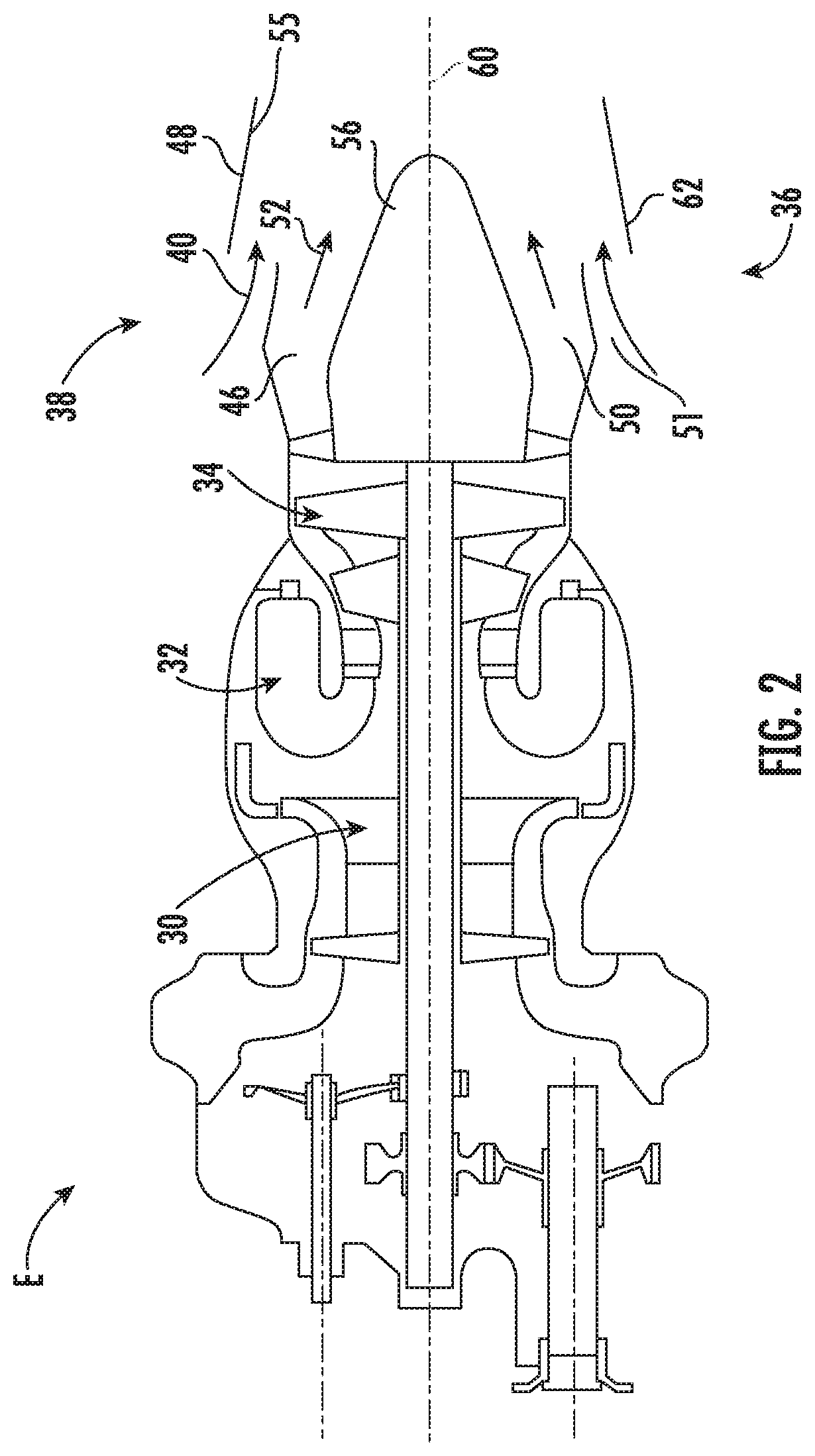
An exhaust system for an engine includes an exhaust nozzle located adjacent an outlet end of the engine to receive a primary flow of exhaust gasses expelled from the engine, an inlet opening formed between the exhaust nozzle and the outlet end of the engine through which a secondary flow is provided to the exhaust nozzle, and a vortex generator arranged within the exhaust system at a position where both the primary flow and the secondary flow are present. The vortex generator interrupts at least one of the primary flow and the secondary flow.

Description

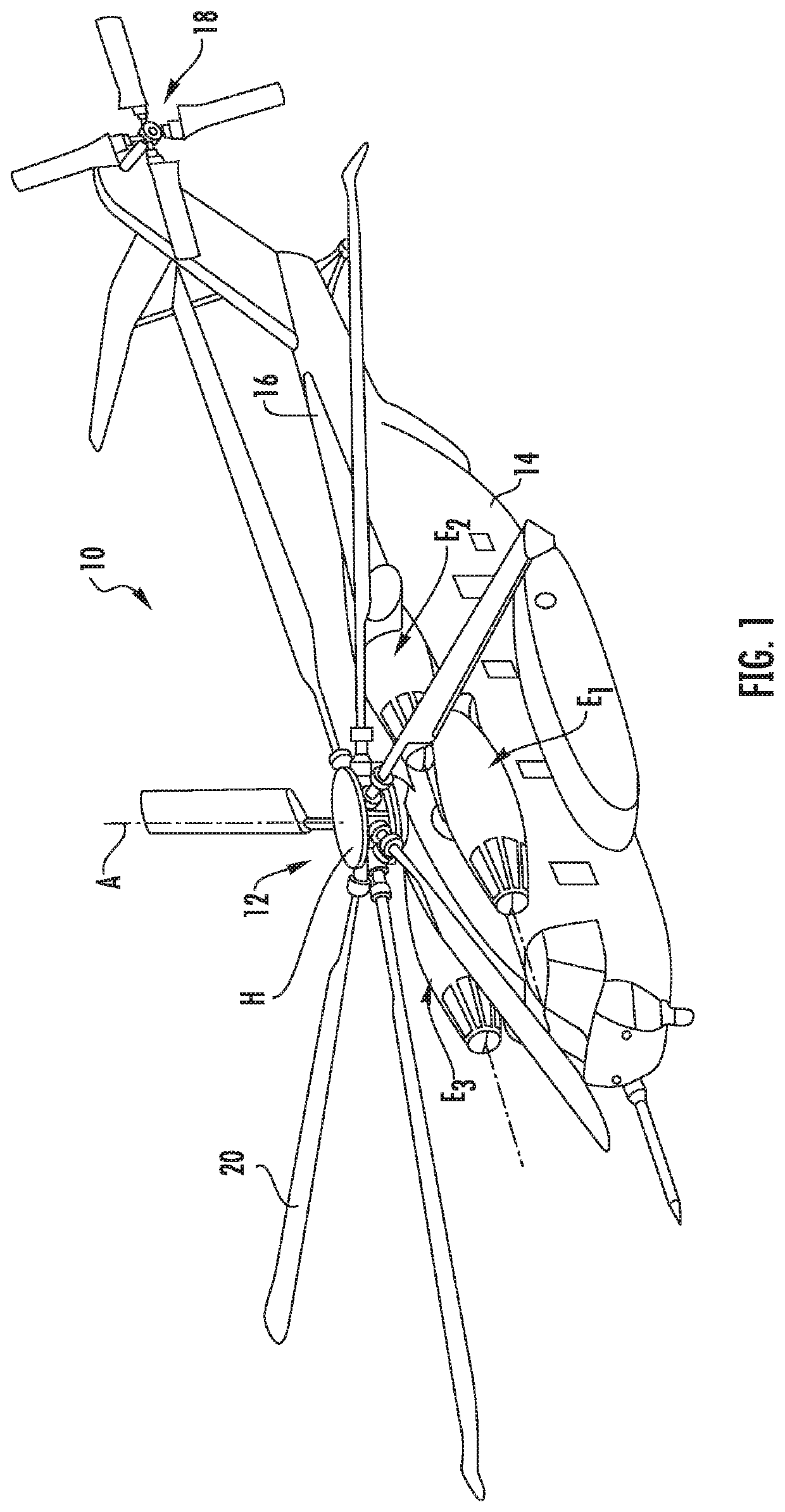
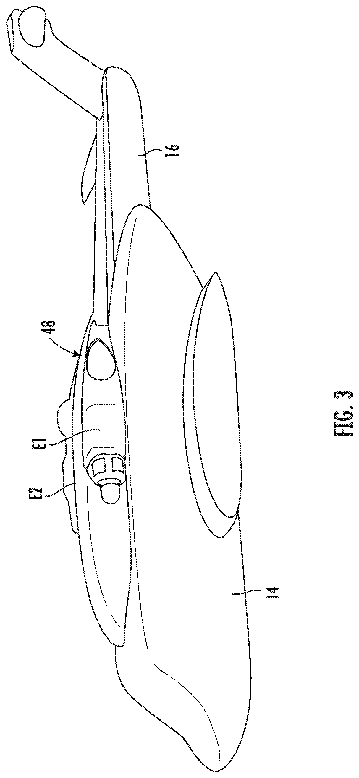
BACKGROUND[0001]Embodiments of the disclosure relate to a turbine engine, and more particularly, to an exhaust duct for use with a turboshaft turbine engine of a rotary wing aircraft.[0002]Rotary-wing aircraft commonly use one or more turboshaft engines to drive rotation of the primary rotary device, in addition to supplying the vehicle's subsystems with power. The exhaust of the turboshaft engine is not utilized for momentum thrust in rotary-wing applications.[0003]Engine performance is maximized when the exhaust duct design returns the high pressure, high temperature gas turbine exhaust air to relatively cool, ambient conditions without causing further increases to the pressure of the turbine outlet, referred to herein as “backpressure.” High backpressure downstream of the turboshaft engine outlet at an operating point directly reduces engine system efficiency. Separation and inadequate diffusion of the turboshaft engine exhaust air caused by the exhaust duct design are primary ca...

Claims


Application Information

Patent Timeline
Patent Type & Authority Applications(United States)
IPC IPC(8): F01D9/02
CPCF01D9/02F05D2250/11F05D2240/127F02K1/46F02K1/36
Inventor SIMONETTI, JOSEPH LAWRENCELAMB, JR., DONALD W.BOWLES, PATRICK ORMANDE
Owner SIKORSKY AIRCRAFT CORP
Learn More