
System, device and method for ventilation

A technology of air supply unit and diffuser, which is applied in air conditioning system, space heating and ventilation, heating methods, etc., and can solve problems such as low air flow rate

Inactive Publication Date: 2008-11-19
JOHNSON MEDICAL DEV
View PDF5 Cites 0 Cited by
  • Summary
  • Abstract
  • Description
  • Claims
  • Application Information

AI Technical Summary

Problems solved by technology

The purpose of this invention is to solve the problem of keeping the air at a constant low velocity as it travels through the room, preventing dust and other particles from being entrained

Method used


Image

  • System, device and method for ventilation
  • System, device and method for ventilation
  • System, device and method for ventilation

Examples


Embodiment Construction

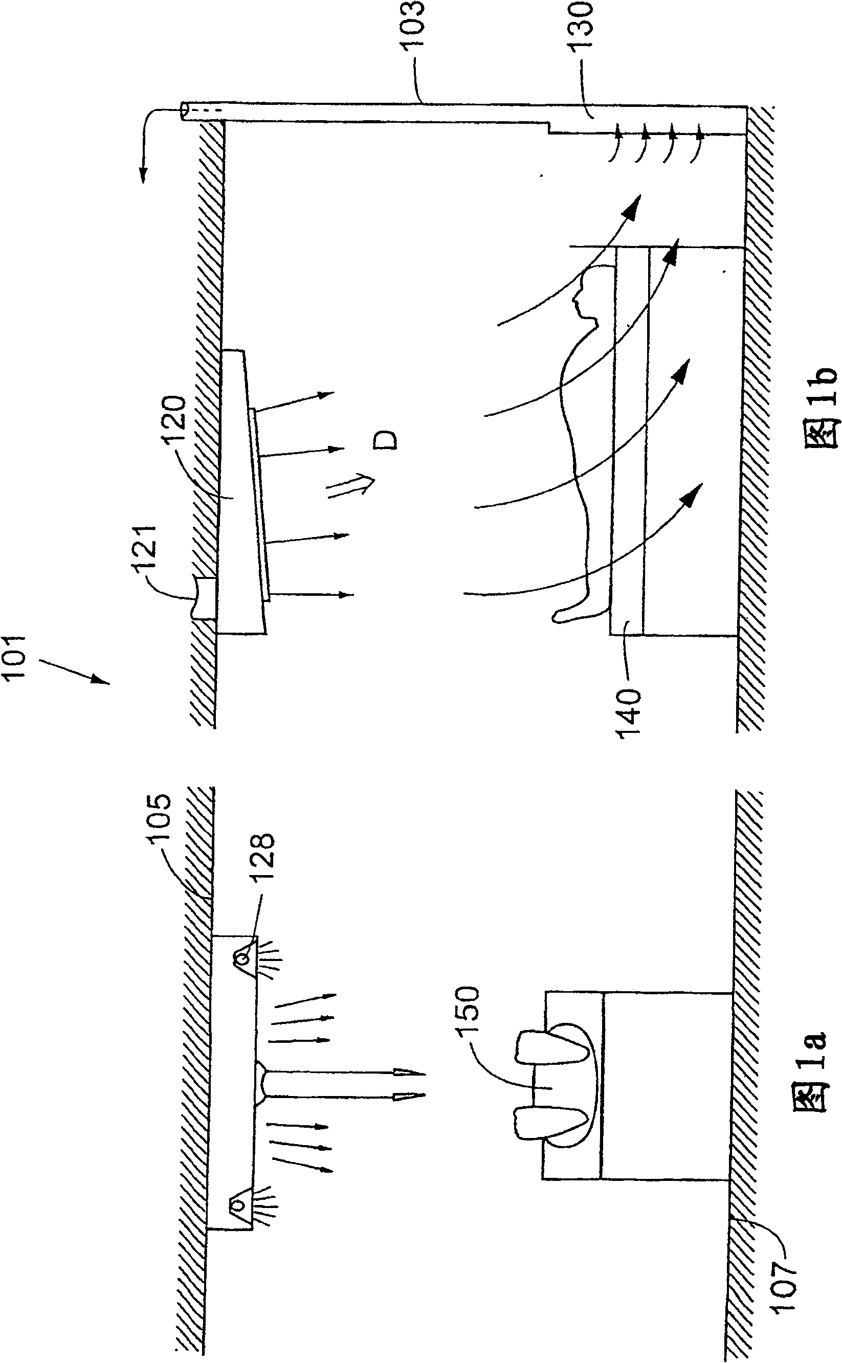
[0026] A preferred embodiment is shown in Figures 1a and 1b. The room 101 with the walls 103 , the suspended ceiling 105 and the floor 107 is provided with an air-conditioning system including at least one air supply unit 120 and at least one low-speed exhaust unit 130 . The air supply unit 120 is located in the ceiling 105 above the hospital bed 140 and is used to supply conditioned air to the patient 150 on the hospital bed 140 .

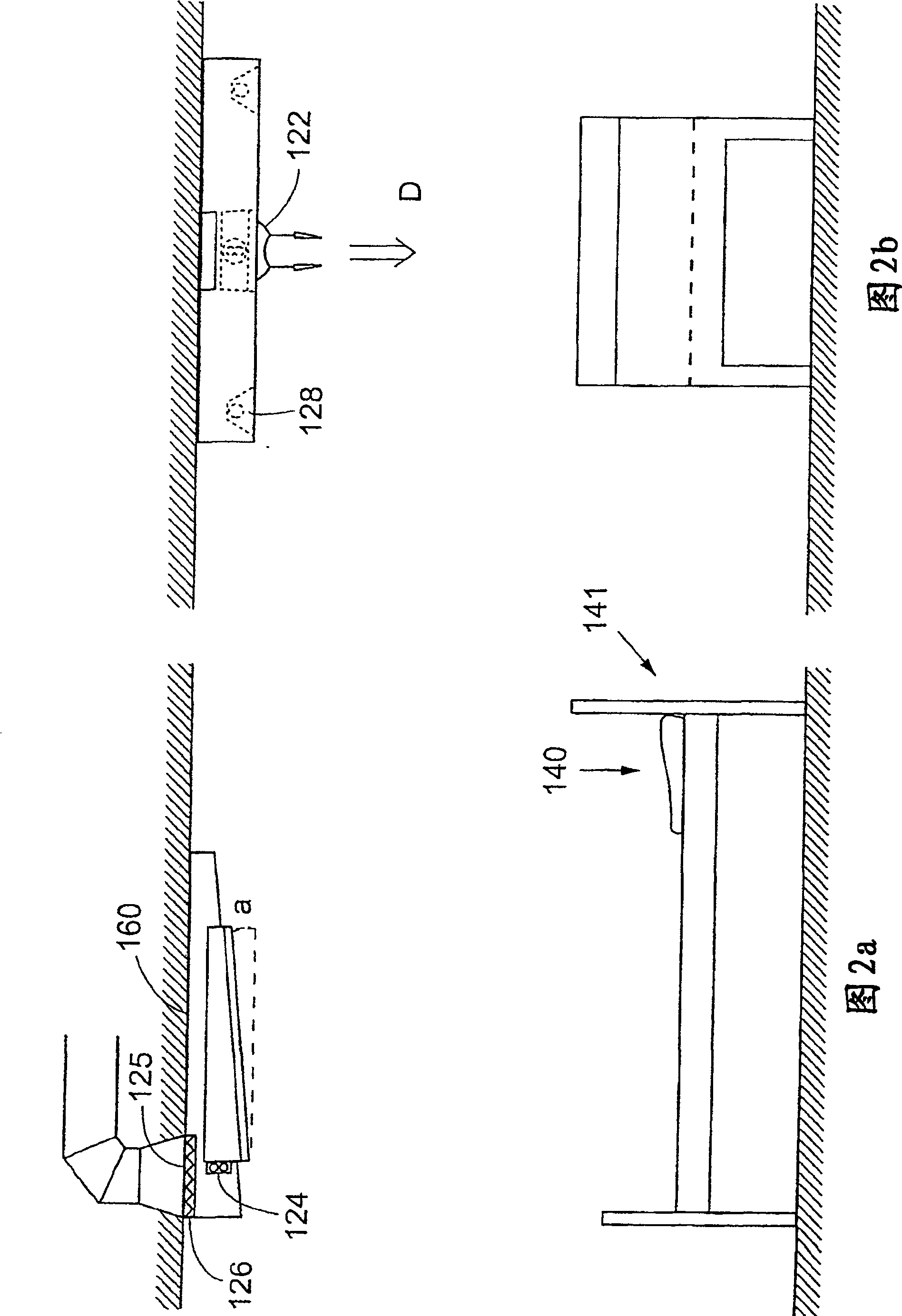
[0027] Figures 2a and 2b show the blower unit 120 of the present invention in more detail. The air blowing unit 120 is provided with an inlet 121 , a guide slit diffuser 122 , a booster fan 124 and an air filter 125 , an opening 126 for placing the filter, some orifices and a lighting unit 128 .

[0028] Air is supplied from the control system to the blower unit 120 . Air enters through inlet 121 and passes through filter 125 where particulates are removed. The air is then diffused inside the blower unit 120 . A portion of the air enters the s...


PUM


Abstract

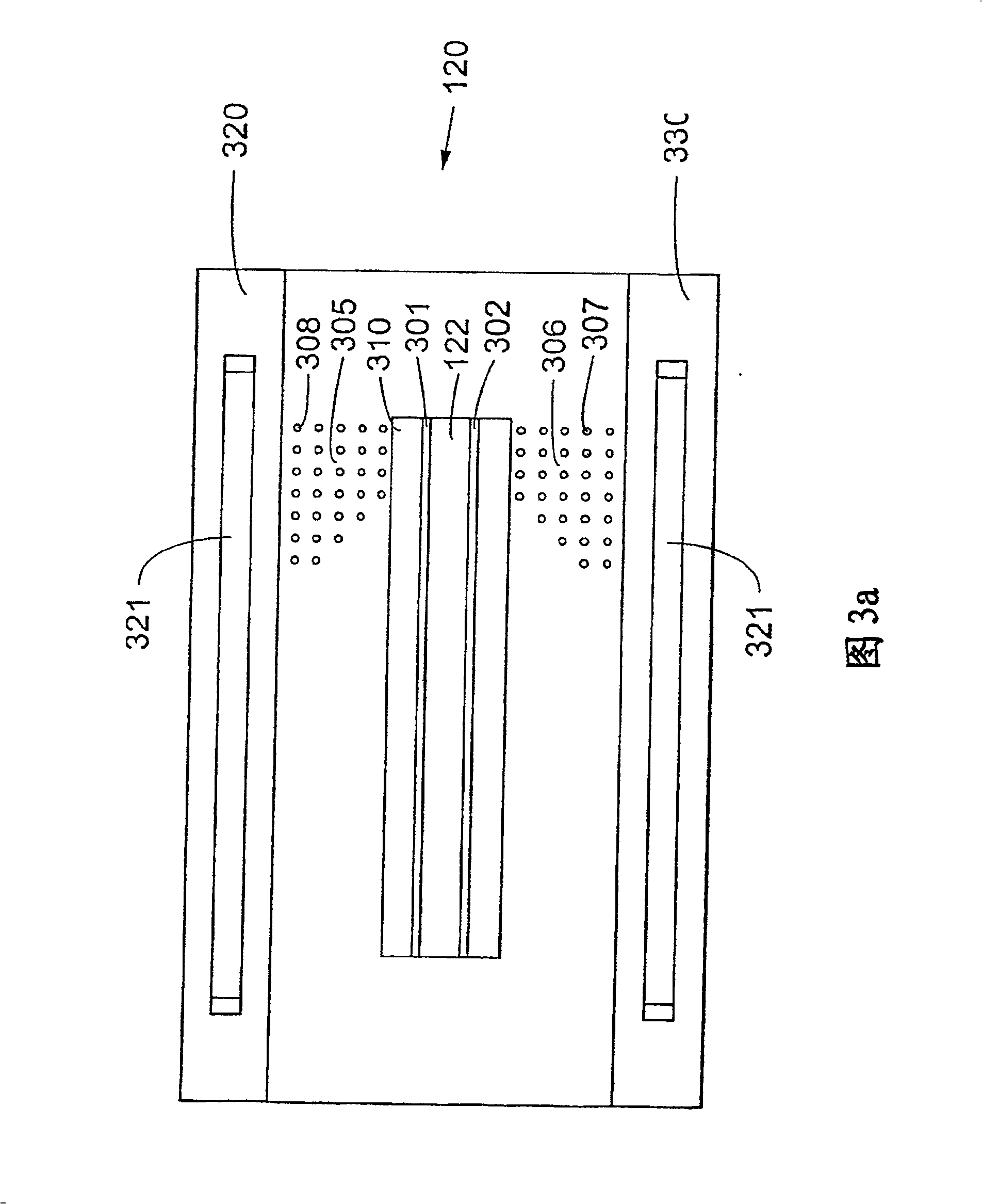
A system and method for ventilating a room having walls ( 103 ), a floor ( 107 ) and a ceiling ( 105 ), and being capable of housing a patient's bed ( 140 ), comprising at least one air supply unit ( 120 ) and one air exhaust unit ( 130 ), where said air inlet unit ( 120 ) comprises a guiding slot diffuser ( 122 ) for guiding an airstream in a certain direction, such that a patient ( 150 ), lying down in said bed on his back, receives said airstream frontally, and that said exhaust unit ( 130 ) is arranged near the floor ( 107 ) and near a head end ( 141 ) of the bed ( 140 ) such that air is arranged to leave the room after having ventilated the patient ( 150 ). The air supply unit is also provided with a booster fan ( 124 ) arranged in air communication with the guiding slot diffuser ( 122 ) such that fresh air can be forced through the diffuser ( 124 ) by the aid of said booster fan ( 124 ) forming a first airstream and that said first airstream leaves the diffuser bringing with it a larger mass of fresh air leaving the air supply unit via perforated sheets ( 305, 306 ), forming the airstream devised to cool the patient.

Description

technical field [0001] The present invention relates to an air conditioning system, especially a device and method for providing ventilation and air conditioning in hospitals or other places with high requirements for clean air. Background technique [0002] As the airflow in the air conditioning system increases, the risk of disturbances increases and the risk of entraining infectious agents that infect patients in eg a hospital ward increases. Such risks are more pronounced in tropical countries where larger cold airflows are generally required to cool patients for comfort. [0003] A method and apparatus for supplying clean air to an operating room is disclosed in WO 86 / 06460 to Nilsson. The apparatus comprises: a central supply part for controlling the carrier bundles directed to said area; and at least two auxiliary air supply parts adjacent to said central supply part for controlling the carrier bundles in the area surrounding said region Auxiliary air jets are suppl...

Claims


Application Information

Patent Timeline
Patent Type & Authority Patents(China)
IPC IPC(8): A61G10/02F24F3/16A61G13/00
CPCA61G13/108F24F3/1607F24F3/163
Inventor A·尼尔松
Owner JOHNSON MEDICAL DEV
Learn More