rotary valve

A rotary valve and rotor technology, applied in the field of rotary valves, can solve the problems of serious accumulation and achieve the effect of preventing adhesion and easy cleaning

Active Publication Date: 2016-09-28
FUJIWARA TECHNO ART CO LTD
View PDF8 Cites 2 Cited by
  • Summary
  • Abstract
  • Description
  • Claims
  • Application Information

AI Technical Summary

Problems solved by technology

Therefore, once a new material is put on the unpeeled material, the accumulation of the gradually adhered material will become more serious.

Method used


Image

  • rotary valve
  • rotary valve
  • rotary valve

Examples


Embodiment Construction

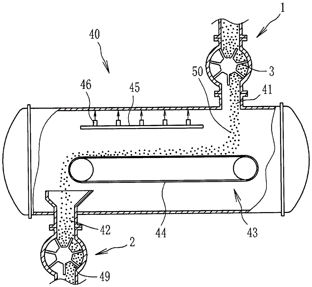
[0048] An embodiment of the present invention will be described below with reference to the drawings. figure 1 It is a block diagram of the pressure cooking apparatus 40 provided with the rotary valve 1 which concerns on one Example of this invention. The pressure cooking device 40 is used to cook the raw material 50 in steam. The raw material 50 is, for example, grain raw materials such as round soybeans, crushed soybeans, defatted soybeans, flat soybeans, bran, rice, and wheat. Among them, round soybeans, crushed soybeans, defatted soybeans, and flat soybeans are mainly used for brewing soy sauce.

[0049] The pressure cooking device 40 is provided with an input port 41 and a discharge port 42 for the raw material 50 . The rotary valve 1 is installed in the input port 41 , and the rotary valve 2 is installed in the discharge port 42 . A mesh conveyor belt 43 for transporting raw materials 50 is arranged in the pressure cooking device 40 . The mesh conveyor 43 includes a ...


PUM


Abstract

PROBLEM TO BE SOLVED: To provide a rotary valve capable of enhancing the certainty of the adhesion prevention of raw materials.SOLUTION: A rotary valve 1 transporting raw materials to an input port of a pressurizing and steaming device includes: a supply port 5 for the raw materials; a discharge port 6 for the raw materials; a casing 4 in which an inner peripheral surface 11 is formed between the supply port 5 and the discharge port 6; a rotor 3 forming a plurality of pockets 10 in the casing 4 and rotated in the casing 4; and a steam supply port 15 for injecting steam into the pockets 10. The steam supply port 15 is formed at the inner peripheral surface of the casing 4 at a side where the rotor 3 is returned from the discharge port 6 to the supply port 5 and formed in a position where the steam is injected into the pockets 10 opened to the discharge port 6.

Description

technical field [0001] The present invention relates to a rotary valve for transferring raw materials to an inlet of a pressure cooking device. Background technique [0002] In a pressure cooker that cooks raw materials, the raw materials are pressure-cooked in water vapor. The pressure cooking device is provided with an inlet for feeding raw materials into the pressure cooking device, and a rotary valve is used to transfer the raw materials to the inlet. Since the airtightness of the rotary valve is high, the raw material can be transferred to the inlet while maintaining the internal pressure of the pressure cooker. [0003] The rotary valve is provided with a raw material supply port and a raw material discharge port, and a rotor rotates in a casing, and grooves ("ポケツト") are formed on the rotor. The raw material is supplied to the groove opened toward the supply port, is transferred to the discharge port as the rotor rotates, and falls from the groove opened to the disch...

Claims


Application Information

Patent Timeline
Patent Type & Authority Patents(China)
IPC IPC(8): B65G29/00
Inventor 狩山昌弘藤原惠子矢泽真裕
Owner FUJIWARA TECHNO ART CO LTD
Why Eureka
Try Eureka