Apparatus, system, and method for use in fluid filling apparatus inspection

Active Publication Date: 2020-01-30
HONDA MOTOR CO LTD
View PDF0 Cites 2 Cited by
  • Summary
  • Abstract
  • Description
  • Claims
  • Application Information

AI Technical Summary

Benefits of technology

This patent describes a device for testing brakes. It includes a vessel with two chambers and two valves to control the flow of brake fluid. A first sensor measures the pressure inside the chamber while a second sensor measures the negative pressure inside the chamber. The device also includes a filling apparatus that can pressurize the chamber. By monitoring the pressure changes, the system can inspect the brake fluid filling process. Overall, this device helps to ensure the brakes are properly filled and function properly.

Problems solved by technology

However, if malfunctions occur during the air removal or fluid filling cycles, it may be difficult to determine the source of the malfunctions.

Method used


Image

  • Apparatus, system, and method for use in fluid filling apparatus inspection
  • Apparatus, system, and method for use in fluid filling apparatus inspection
  • Apparatus, system, and method for use in fluid filling apparatus inspection

Examples


Embodiment Construction

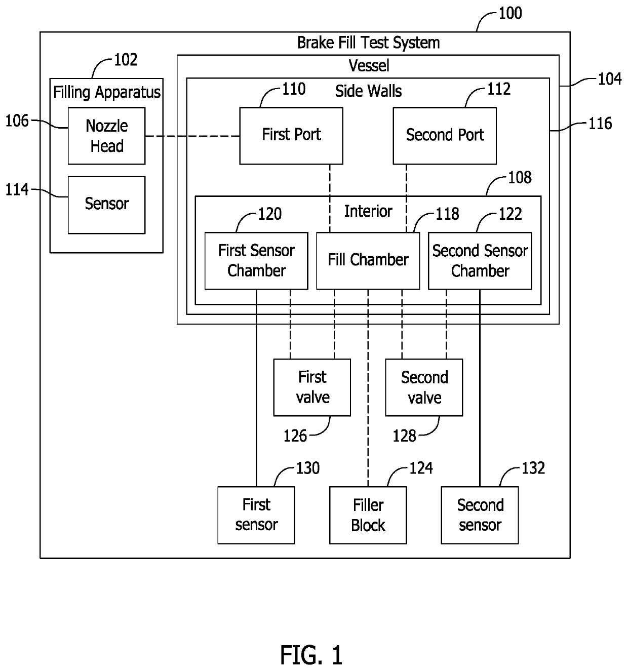
[0010]The embodiments described herein relate generally to systems and methods of inspecting a brake fluid filling apparatus. More specifically, the system described herein includes a test vessel designed to simulate a fluid reservoir of a motor vehicle as a form of control for the brake fluid filling apparatus. For example, the test vessel has an interior sized to simulate a known volume of a brake fluid system, and the test vessel has side walls that are resistant to deformation when the interior is pressurized by the brake fluid filling apparatus. During an inspection operation, the brake fluid filling apparatus mates with the test vessel as though it is performing a normal fluid filling operation on a brake system of a motor vehicle.

[0011]During normal fluid filling operations, typically a vacuum cycle is performed to remove air from the brake fluid system, and a filling cycle is then performed to fill the brake fluid system with a predetermined volume of fluid. In the example e...


PUM


Abstract

A brake fill test apparatus that includes a vessel including an interior having a fill chamber, a first sensor chamber, and a second sensor chamber. The vessel also includes at least one port that provides access to the fill chamber. A first valve is configured to provide selective flow communication between the fill chamber and the first sensor chamber, and a second valve is configured to provide selective flow communication between the fill chamber and the second sensor chamber. A first sensor is coupled within the first sensor chamber and a second sensor is coupled within the second sensor chamber. The first sensor is configured to monitor a positive gauge pressure within the interior and the second sensor is configured to monitor a negative gauge pressure within the interior.

Description

BACKGROUND[0001]The field of the present disclosure relates generally to fluid systems in a vehicle and, more specifically, to systems and methods of inspecting a brake fluid filling apparatus.[0002]A known process step in the manufacture of motor vehicles includes adding fluids to hydraulic, cooling, and lubricating systems of the vehicle. For example, fluids must be added to the engine, transmission, steering system, cooling system, and brake system of the vehicle to enable the vehicle to operate properly. Vehicle fluid filling operations may be performed with an automated or robotic filling tool, which facilitates filling the various systems with the proper amount of fluid in a rapid and repeatable manner. In at least some known filling operations, such as those in which brake fluid is introduced into the brake system, air must be removed from the brake system before brake fluid is introduced therein to facilitate improving the responsiveness of the brakes in the vehicle. However...

Claims


Application Information

Patent Timeline
IPC IPC(8): G01L15/00
CPCG01L15/00B60T17/222B60T17/043
Inventor HILL, ROBERT LEEREEVES, JAMES ALLEN
Owner HONDA MOTOR CO LTD
Why Eureka
Try Eureka