Lockable torque wrench with adjustment indication

Active Publication Date: 2020-02-06
OGC TORQUE
View PDF4 Cites 2 Cited by
  • Summary
  • Abstract
  • Description
  • Claims
  • Application Information

AI Technical Summary

Benefits of technology

[0010]With such configuration, when the user adjusts the torque value of the torque wrench, with an adjustment indication provided by the switch sensation produced by the rolling pillar, which is pressed by the pressin

Problems solved by technology

However, when visually confirming the scale, a difference between the exact torque value and the visually acquired torque value s

Method used


Image

  • Lockable torque wrench with adjustment indication
  • Lockable torque wrench with adjustment indication
  • Lockable torque wrench with adjustment indication

Examples


Example

[0019]The aforementioned and further advantages and features of the present invention will be understood by reference to the description of the preferred embodiment in conjunction with the accompanying drawings where the components are illustrated based on a proportion for explanation but not subject to the actual component proportion.

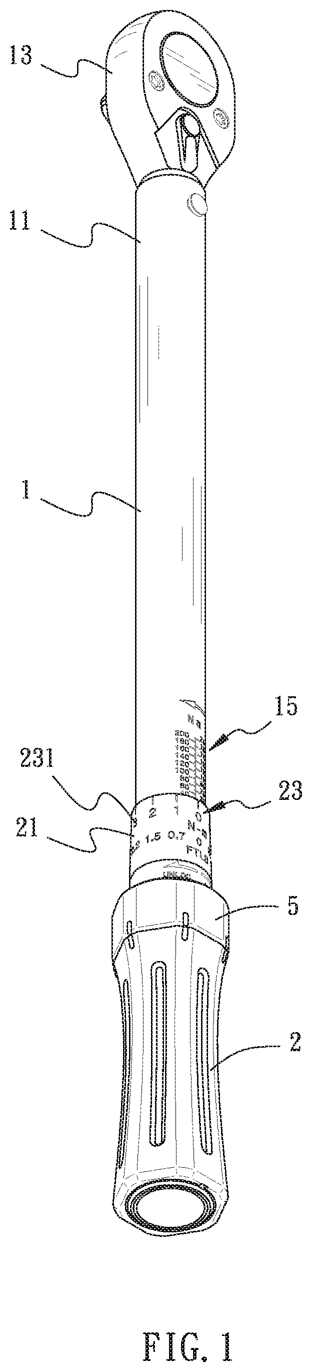
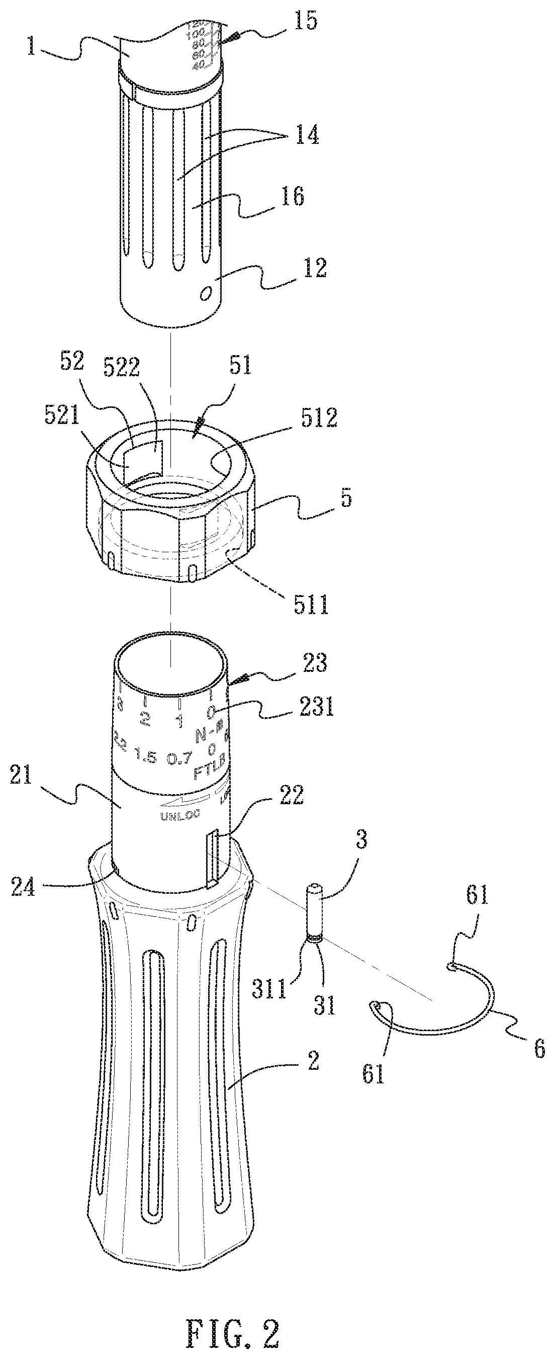
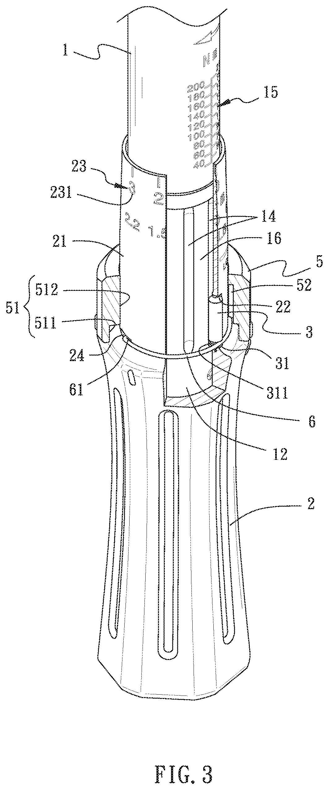
[0020]Referring to FIG. 1 to FIG. 8, a lockable torque wrench with adjustment indication in accordance with an embodiment of the present invention comprises a rod body 1, a handle 2, a rolling pillar 3, a rolling pillar 4, a rotation ring 5, and a pressing member. In a preferred embodiment, the pressing member is a clamp ring 6.

[0021]Referring to FIG. 1 to FIG. 2, the rod body 1 is formed in an elongate rod having a first end 11 and a second end 12, with a driving head 13 disposed at the first end 11 of the rod body 1. Also, a plurality of position limiting grooves 14 are disposed at the outer periphery of the rod body 1 in adjacent to the second end 1...


PUM


Abstract

A lockable torque wrench with adjustment indication includes a rod body, a handle, a plurality of rollers having a rolling pillar, a rotation ring, and a pressing member. The rod body is combined into the handle and rotatable to protrude or retract against the handle for adjusting the torque. The rotation ring is disposed on an extension tube of the handle and mounted around the rollers. The rotation ring is switched between a locked and a relax positions. The pressing member has combination portions at two sides of the extension tube, and permanently engages the rolling pillar. In an ascend position, the rolling pillar is pressed toward the rod body by the prestress force supporting the pressing member. When meeting a position limiting groove, the rolling pillar is pressed to lower in the position limiting groove, providing a switch sensation formed for the user.

Description

BACKGROUND OF THE INVENTION1. Field of the Invention[0001]The present invention relates to torque wrenches, and more particularly, to a lockable torque wrench with adjustment indication.2. Description of the Related Art[0002]Referring to TW patent M515937, a lock ring structure of torque wrench is disclosed, wherein the main body thereof comprises an inner tube externally mounted with an outer tube, and the outer tube comprises two positioning members and a position limiting member, with a lock ring mounted around the outer tube. The lock ring includes an inner ring and an outer ring. The inner ring has one allowance groove corresponding to each position limiting member. The inner ring has a position limiting groove corresponding to the position limiting member, with two position limiting blocks disposed in the position limiting groove. When the lock ring rotates with respect to the main body, the position limiting member is able to be engaged with either position limiting block. Al...

Claims


Application Information

Patent Timeline
IPC IPC(8): B25B23/142
CPCB25B23/1427
Inventor GUO, WUN-JIN
Owner OGC TORQUE
Why Eureka
Try Eureka