Beam Adjustment Method and Three-Dimensional Powder Bed Fusion Additive Manufacturing Apparatus

Pending Publication Date: 2021-12-30
JEOL LTD
View PDF0 Cites 2 Cited by
  • Summary
  • Abstract
  • Description
  • Claims
  • Application Information

AI Technical Summary

Benefits of technology

[0012]By the beam adjustment method and the three-dimensional PBF-AM apparatus of

Problems solved by technology

Therefore, in the technology disclosed in JP 54-68149 A, a temperature of the Faraday cup is increased by the electron beam, positions of

Method used


Image

  • Beam Adjustment Method and Three-Dimensional Powder Bed Fusion Additive Manufacturing Apparatus
  • Beam Adjustment Method and Three-Dimensional Powder Bed Fusion Additive Manufacturing Apparatus
  • Beam Adjustment Method and Three-Dimensional Powder Bed Fusion Additive Manufacturing Apparatus

Examples


Example

1. First Embodiment

[0030]1-1. Configuration of Three-Dimensional PBF-AM Apparatus

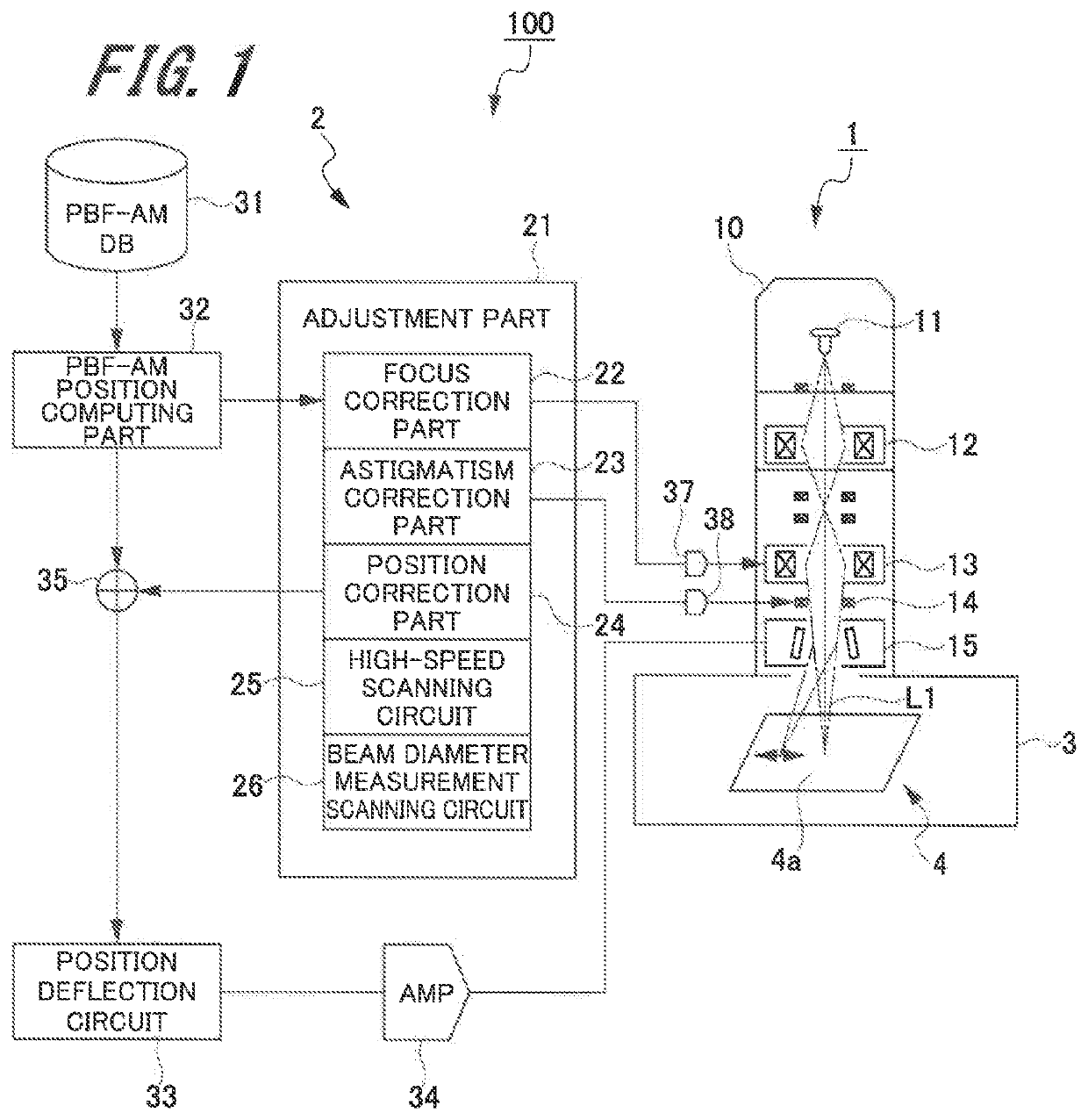
[0031]First, a three-dimensional PBF-AM apparatus according to a first embodiment (hereinafter, referred to as “the present embodiment”) of the present invention will be described with reference to FIG. 1.

[0032]FIG. 1 is an explanatory diagram schematically illustrating the three-dimensional PBF-AM apparatus of the present embodiment.

[0033]The apparatus illustrated in FIG. 1 is a three-dimensional PBF-AM apparatus which irradiates, for example, a powder material made of metal such as titanium, aluminum, and iron with an electron beam to melt the powder material and stacks images of the solidified powder material, thereby modeling a solid object.

[0034]As illustrated in FIG. 1, the three-dimensional PBF-AM apparatus 100 has an irradiation unit 1 which radiates an electron beam L1, a control part 2 which controls the irradiation unit 1, and a build chamber 3. Inside the build chamber 3, a build unit 4 is i...

Example

2. Second Embodiment

[0102]Next, with reference to FIG. 16, a beam adjustment method according to a second embodiment will be described.

[0103]FIG. 16 is an explanatory diagram showing the beam adjustment method according to the second embodiment.

[0104]The beam adjustment method according to the second embodiment is different from the beam adjustment method according to the first embodiment in that beam adjustment work is performed without providing a shielding plate 55 for an adjustment unit. Therefore, parts which are in common with those in the beam adjustment method and the three-dimensional PBF-AM apparatus according to the first embodiment are denoted by the same reference signs and overlapping description is omitted.

[0105]As shown in FIG. 16, in the beam adjustment method according to the second embodiment, upon starting beam adjustment processing, an adjustment part 21 performs high-speed scanning processing (normal processing) in which an electron beam L1 is scanned at a high...


PUM

PropertyMeasurementUnit
Lengthaaaaaaaaaa
Volumeaaaaaaaaaa
Diameteraaaaaaaaaa

Abstract

A beam adjustment method includes: installing, on an irradiation surface to which an electron beam is radiated, a detection part having a Faraday cup catching electrical charges of the electron beam, and installing, on a side of an electron gun further than the detection part, a shielding plate having opening holes through which the electron beam is passable. The method includes causing, upon performing beam diameter measurement processing, the electron beam to pass through the opening holes, and radiating the electron beam to the Faraday cup. In addition, the method includes radiating, upon performing normal processing, the electron beam to the shielding plate.

Description

CROSS-REFERENCE TO RELATED APPLICATION[0001]This application claims priority to Japanese Patent Application No. 2020-088419 filed May 20, 2020, the disclosure of which is hereby incorporated by reference in its entirety.BACKGROUND OF THE INVENTIONField of the Invention[0002]The present invention relates to a beam adjustment method for adjusting an electron beam and a three-dimensional powder bed fusion additive manufacturing (PBF-AM) apparatus for modeling by superposing thinly bedded layers of a powder material one by one on a stage.Description of Related Art[0003]In an apparatus which radiates an electron beam, work for adjusting a beam diameter and an irradiation position of the electron beam is performed. As such a technology for adjusting the electron beam, for example, there is a technology disclosed in JP 54-68149 A. In JP 54-68149 A, the technology which irradiates a Faraday cup catching electrical charges of the electron beam is disclosed.[0004]In addition, in recent years,...

Claims


Application Information

Patent Timeline
IPC IPC(8): H01J37/147H01J37/09B33Y30/00B33Y50/00B22F10/80B22F12/41B23K15/00B23K15/02
CPCH01J37/1474H01J37/09B33Y30/00B33Y50/00B23K15/02B22F12/41B23K15/0086B23K15/002B22F10/80H01J2237/1536H01J2237/24405H01J2237/24542H01J2237/30433H01J2237/30461H01J37/244H01J37/304H01J37/305B22F10/28B22F10/31B22F2999/00B33Y50/02Y02P10/25B22F10/36B22F12/40
Inventor EN, SHIOSATO, TAKASHI
Owner JEOL LTD
Why Eureka
Try Eureka