Imaging apparatus

Inactive Publication Date: 2017-11-16
PANASONIC INTELLECTUAL PROPERTY MANAGEMENT CO LTD
View PDF11 Cites 2 Cited by
  • Summary
  • Abstract
  • Description
  • Claims
  • Application Information

AI Technical Summary

Benefits of technology

[0031]According to the present invention, adhesion of dust and the like to a light receiving surface of a solid-state image sensing device

Problems solved by technology

It is necessary to assemble the lens of the imaging apparatus disclosed by Patent Literature 1 in a clean room so as to prevent dust and the like from adher

Method used


Image

  • Imaging apparatus
  • Imaging apparatus
  • Imaging apparatus

Examples


Example

[0035]A preferred embodiment for practicing the present invention will now be described in detail with reference to the accompanying drawings.

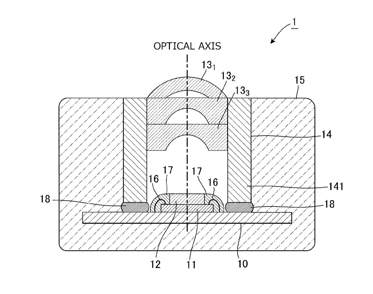
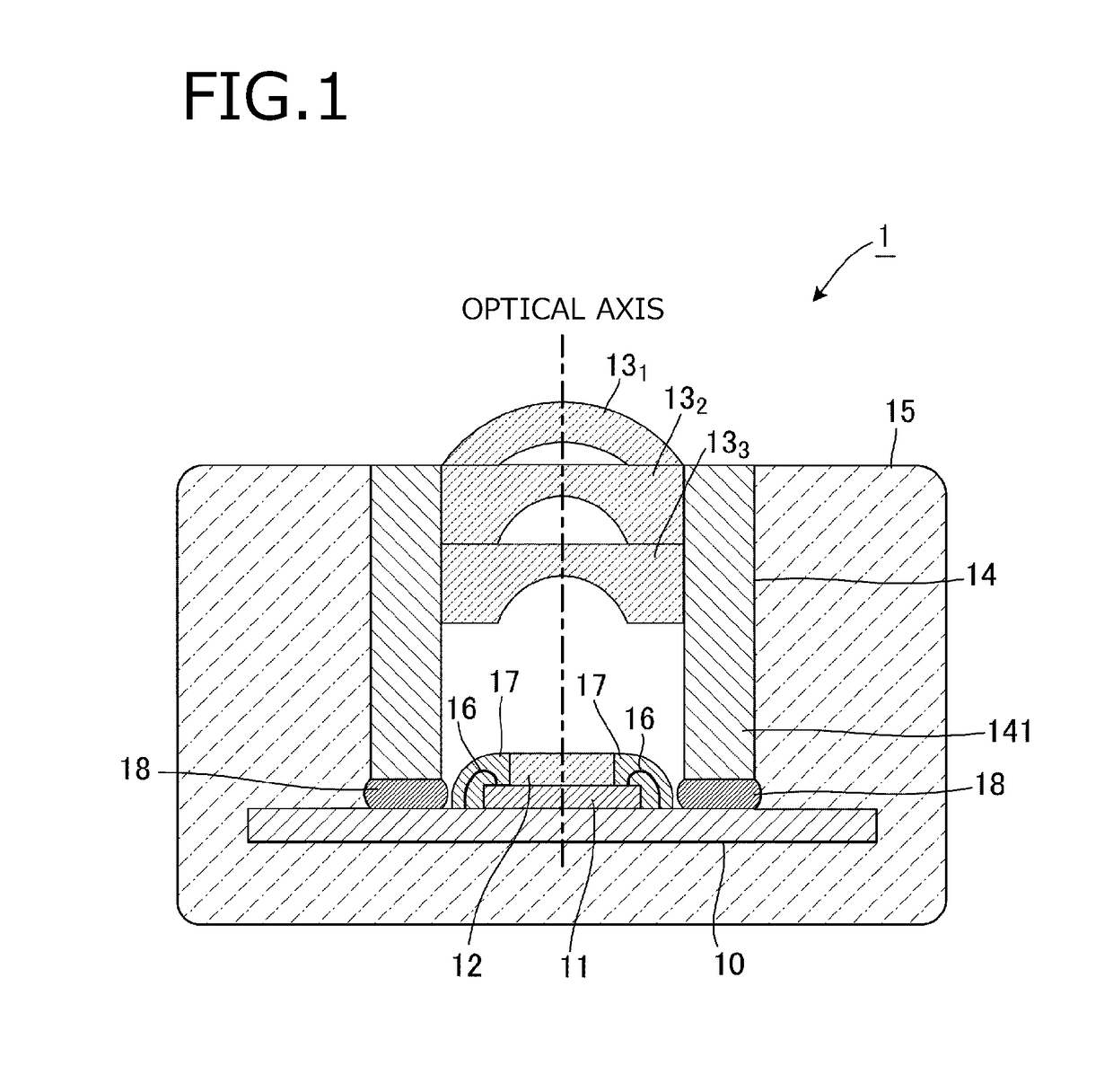
[0036]FIG. 1 is a vertical cross-sectional view illustrating the structure of an imaging apparatus according to one embodiment of the present invention. In this drawing, the imaging apparatus 1 of the present embodiment includes a circuit board 10, a solid-state image sensing device 11 disposed in a center portion on an upper surface of the circuit board 10, a glass plate 12 disposed on the upper surface of the solid-state image sensing device 11, a cylindrical lens barrel 14 disposed on the upper surface of the circuit board 10 and housing three lenses 131 to 133 therein, and a holding member 15 for sealing, with resin, a region surrounding and including the lens barrel 14 and a region surrounding and including the circuit board 10.

[0037]The circuit board 10 and the solid-state image sensing device 11 are electrically connected to each other ...


PUM


Abstract

An imaging apparatus includes a circuit board, a solid-state image sensing device disposed on an upper surface of the circuit board, a lens disposed above and spaced from the solid-state image sensing device, and a lens barrel disposed on the upper surface of the circuit board and that houses the tens. The lens barrel has a leg section which is at least a part of the lens barrel other than a part of the lens barrel housing the lens, and the leg section is connected to the circuit board with an adhesive applied in a large application amount to have a thickness.

Description

TECHNICAL FIELD[0001]The present invention relates to an imaging apparatus using a solid-state image sensing device such as a CCD (Charge Coupled Device) image sensor or a CMOS (Complementary Metal Oxide Semiconductor) image sensor.BACKGROUND ART[0002]Recently, in accordance with increased performance of an imaging apparatus using a solid-state image sensing device as one described above, electronic equipment equipped with an imaging apparatus including an autofocus mechanism has become widely used.[0003]Patent Literature 1 discloses an imaging apparatus capable of adjusting its position in an optical axis direction by causing a leg section of a lens to abut against a region excluding a light receiving surface of a solid-state image sensing device.[0004]It is necessary to assemble the lens of the imaging apparatus disclosed by Patent Literature 1 in a clean room so as to prevent dust and the like from adhering to the light receiving surface of the solid-state image sensing device, a...

Claims


Application Information

Patent Timeline
IPC IPC(8): H04N5/225H04N5/335H04N5/232H04N9/04
CPCH04N5/2258H04N5/335H04N5/2252H04N5/23245H04N9/045G03B17/02G02B7/021G02B13/001G02B27/62H04N23/55H04N23/45H04N23/51H04N25/00H04N23/667
Inventor IDA, TETSUYAINAGAKI, TATSUHIKO
Owner PANASONIC INTELLECTUAL PROPERTY MANAGEMENT CO LTD
Why Eureka
Try Eureka