Valve closure for a piston compressor valve and method for operating the valve closure

a valve and compressor technology, applied in the field of valves for piston compressors, can solve the problems of reducing the sealing function of the valve, affecting the operation of the valve, so as to reduce the force, reduce the force, and reduce the mass inertia

Active Publication Date: 2020-02-06
BURCKHARDT COMPRESSION AG
View PDF0 Cites 0 Cited by
  • Summary
  • Abstract
  • Description
  • Claims
  • Application Information

AI Technical Summary

Benefits of technology

[0015]The valve closure of the piston compressor valve, comprising the valve seat and the closing element, is preferably designed in such a manner that the valve seat has a center and a plurality of passage openings which are disposed so as to be spaced apart in the circumferential direction and run radially toward the center, and that the closing element has a plurality of radial arms and a rotation axis, wherein the arms run so as to be radial to the rotation axis, and wherein each passage opening is assigned one closing arm which is designed to be wide in such a manner that said closing arm can completely cover the passage opening in a closed position, and in an open position cover said passage opening to an ideally minor extent or not at all. The closing arms are designed in such a manner that said closing arms have a cross-sectional face that decreases toward the periphery, and on account thereof have a mass reducing toward the periphery in that the closing arms are designed so as to be thinner toward the periphery, for example. A closing element comprising closing arms of this type toward the periphery has a particularly minor mass and therefore has a reduced mass inertia, which is why minor forces are required in order to activate the closing element, that is to say to accelerate and decelerate, so as to switch the closing element back and forth between a closing position and an open position. The reduced mass inertia has the additional advantage that lower forces are required for accelerating the closing element in the profile direction of the rotation axis, or that the closing element can be moved more rapidly, or in a shorter time, respectively, in the profile direction of the rotation axis. The closing element is particularly preferably made from a plastics material and preferably comprises a fiber reinforcement, preferably carbon fibers, so that the closing element has a minor mass.
[0016]The closing element comprising a plurality of radial arms moreover has the advantage that the arms on the peripheries thereof are not mutually connected to one another such that each closing arm can place itself individually onto the passage opening so that each closing arm can better correct any irregularities or traces of wear that are potentially present on the passage opening or on the closing arm, in that each closing arm can bear individually on the valve seat. The cross-sectional face that decreases toward the periphery preferably has the result that the closing arm moreover has a reduced flexural rigidity toward the periphery, this resulting in the advantage that the closing arm can particularly readily adapt to the profile of the valve seat when the closing arm covers the passage opening, this resulting in particularly advantageous sealing.

Problems solved by technology

This known valve has the disadvantages that relatively high wear arises, that opening and closing of the valve takes a relatively long time, and that the sealing function of the valve is reduced over time by virtue of the arising wear.

Method used


Image

  • Valve closure for a piston compressor valve and method for operating the valve closure
  • Valve closure for a piston compressor valve and method for operating the valve closure
  • Valve closure for a piston compressor valve and method for operating the valve closure

Examples


Embodiment Construction

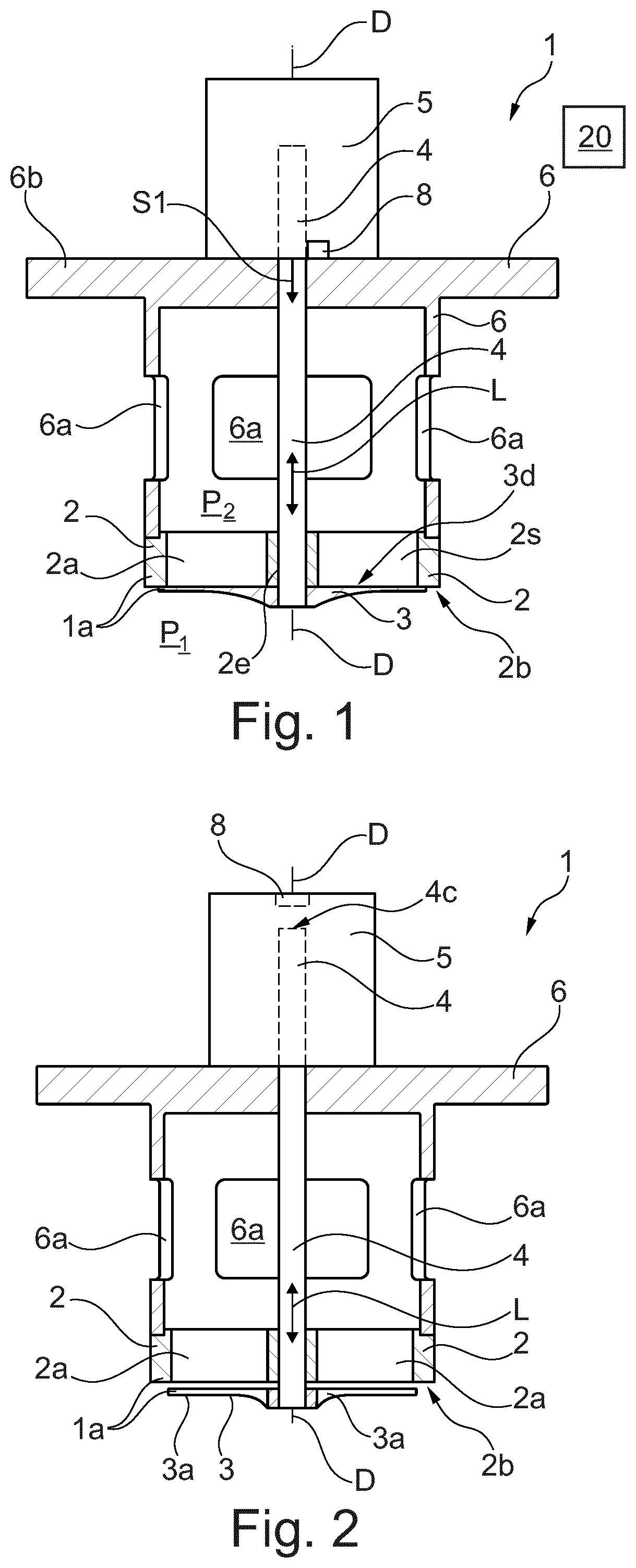
[0057]FIG. 1 shows an actively controlled piston compressor valve 1 comprising a valve seat 2 having a plurality of passage openings 2a, comprising a closing element 3 that for opening and closing the passage openings 2a is rotatable about a rotation axis D, and comprising an actuator drive 5 for rotating the closing element 3. The valve seat 2 has an end side 2b into which the passage openings 2a open out, wherein the closing element 3 is connected to the actuator drive 5 so as to be movable in the profile direction L of the rotation axis D such that the closing element 3 is rotatable about the rotation axis D as well as displaceable in the profile direction L of the rotation axis D in relation to the end side 2b. The shaft 4 is mounted in a bore 2e of the value seat 2 or is an axial guide bearing, respectively. The valve 1 is disposed in a bell housing 6 comprising passage openings 6a and a cover 6b. The closing element 3 is illustrated in a lowered closed position such that the c...


PUM


Abstract

A valve closure for a piston compressor valve including: a valve seat having a plurality of passage openings, a shaft having an axis of rotation (D), and a rotatable closing element connected to the shaft for opening and closing the passage openings, the valve seat having a flat end face, to which the passage openings lead and a center (Z): the passage openings extending radially to the center (Z); and the closing element having a center point (M) and a plurality of closing arms extending radially to the center point (M). The shaft can be rotated about the axis of rotation and can be slid in the extension direction of the axis of rotation extending perpendicularly to the end face and through the center (Z); each closing arm having a sealing surface substantially complementary to the passage openings in accordance with the rotation of the closing element.

Description

[0001]The invention relates to a valve closure for a piston compressor valve as claimed in the preamble of claim 1. The invention furthermore relates to a method for operating a valve closure as claimed in the preamble of claim 16.PRIOR ART[0002]Document WO 01 / 59266A1 discloses a valve for a piston compressor. This valve comprises a valve seat and a rotatable closing element, wherein the closing element, as a function of the rotary position thereof, opens or closes passage openings that are disposed in the valve seat. This known valve has the disadvantages that relatively high wear arises, that opening and closing of the valve takes a relatively long time, and that the sealing function of the valve is reduced over time by virtue of the arising wear.SUMMARY OF THE INVENTION[0003]It is an object of the invention to form a more advantageous valve closure for a piston compressor valve.[0004]This object is achieved by a valve closure comprising the features of claim 1. Dependent claims 2...

Claims


Application Information

Patent Timeline
Patent Type & Authority Applications(United States)
IPC IPC(8): F04B39/10F04B39/08F16K3/08F16K3/10F16K15/06
CPCF04B39/08F16K15/06F16K3/085F16K15/18F16K3/10F04B39/102F04B7/0042F04B7/0046F04B7/0053F04B7/0076F05B2210/12Y10T137/7839Y10T137/7843Y10T137/7842Y10T137/784
Inventor VOSER, ALEXANDRE
Owner BURCKHARDT COMPRESSION AG
Why Eureka
Try Eureka