Radio communication system, network device, and radio communication method

a radio communication system and network device technology, applied in the direction of network traffic/resource management, network topologies, connection management, etc., can solve the problems of changing the existing sequence, unable to know, and complicating the sequence,

Active Publication Date: 2020-02-13
NTT DOCOMO INC
View PDF6 Cites 7 Cited by
  • Summary
  • Abstract
  • Description
  • Claims
  • Application Information

AI Technical Summary

Benefits of technology

[0012]Hence, the present invention has been made in view of the above situation, and an objective thereof is to provide a radio communication system, a network

Problems solved by technology

Thus, for execution of the Dual Connectivity (DC), a network device on the core network, i.e., a functional entity providing a control plane called a CN-CP has a problem that there is no way to know whether to establish a PDN

Method used


Image

  • Radio communication system, network device, and radio communication method
  • Radio communication system, network device, and radio communication method
  • Radio communication system, network device, and radio communication method

Examples


Embodiment Construction

[0031]Next, an embodiment of the present invention will be described based on the drawings. Note that the same or similar reference signs denote the same or similar functions and structures, and descriptions thereof are omitted as appropriate.

(1) Overall Schematic Configuration of Radio Communication System

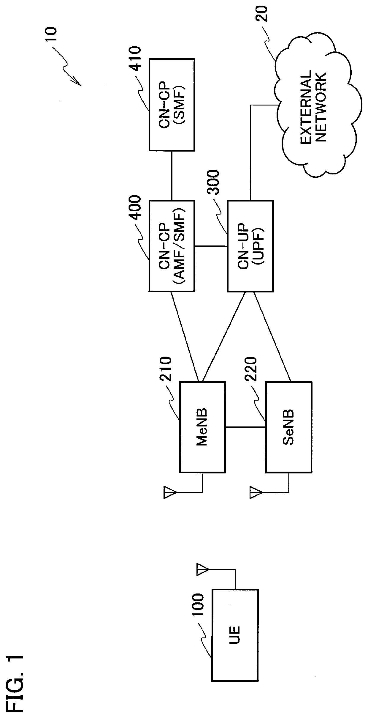
[0032]FIG. 1 is an overall schematic configuration diagram of a radio communication system 10 according to the present embodiment. The radio communication system 10 conforms to “5G”, which is the succeeding system of Long Term Evolution (LTE). Note that the radio communication system 10 may be referred to as FRA (future radio access), the next generation system (NGS), or the 5G system (5GS) for example.

[0033]As illustrated in FIG. 1, the radio communication system 10 includes user device 100 (hereinafter, UE 100), a master radio base station 210 (hereinafter, MeNB 210), a secondary radio base station 220 (hereinafter, SeNB 220), a core network user plane function 300 (hereinafter,...


PUM


Abstract

A radio communication method includes a step in which a MeNB (210) transmits a bearer setup instruction to establish a bearer including a first tunnel and a second tunnel based on a setup request, and a step in which a CN-UP (300) establishes the first tunnel and the second tunnel based on the bearer setup instruction. The CN-UP (300) sets the same identifiers to a TEID on the CN-UP (300) side of the first tunnel and a TEID on the CN-UP (300) side of the second tunnel.

Description

TECHNICAL FIELD[0001]The present invention relates to a radio communication system which includes a master radio base station and a secondary radio base station, a network device, and a radio communication method.BACKGROUND ART[0002]3rd Generation Partnership Project (3GPP) specifies, with the aim of further speeding Long Term Evolution (LTE), LTE-Advanced (hereinbelow, the LTE includes the LTE-Advanced). The 3GPP is also discussing a specification for the new radio (NR) and the next generation system (NGS), which are called 5G (5th generation mobile communication system), for example.[0003]In the discussion for a specification for this next generation system, there has been proposed the flow-based QoS (Quality of Service) framework (for example, Non-Patent Literature 1). Specifically, based on the Flow Priority Indicator (FPI) indicating a degree of priority of an IP flow, scheduling and priority control of the IP flow are performed on an EPS bearer (NGS bearer), which is a logical...

Claims


Application Information

Patent Timeline
IPC IPC(8): H04W76/22H04W76/11H04W28/10H04W76/15
CPCH04W84/20H04W76/11H04W76/22H04W28/10H04W76/15H04W92/045H04W76/12H04L47/24
Inventor MINOKUCHI, ATSUSHIMUTIKAINEN, JARIALI, IRFAN
Owner NTT DOCOMO INC
Why Eureka
Try Eureka