Multifunctional hydrodynamic vortex reactor and method for intensifying cavitation

a hydrodynamic vortex reactor and multifunctional technology, applied in the field of machine building technology, can solve the problems of limited industrial use of such technologies, difficult to achieve the effect of high degree of mixture dispersion

Active Publication Date: 2020-02-20
GALAKA OLEKSANDR +2
View PDF0 Cites 5 Cited by
  • Summary
  • Abstract
  • Description
  • Claims
  • Application Information

AI Technical Summary

Benefits of technology

[0026]The object of the invention is to provide a multifunctional hydrodynamic vortex type reactor (herein also called a “MHVR”) that allows achieving a high degree of mix

Problems solved by technology

As a rule, the grinding process to a size of less than 2 micrometers is quite energy intensive and expensive.
Grinding substances to nanoscale mechanically is practically impossible.
Therefore, the widespread use of such technologies in industry is limited.
Analyzing Vorage, it becomes apparent that its design does not allow obtaining high concentration of power, and therefore a high degree of mixture dispersion of particles (not to mention grinding to a nanoscale) of solid materials in liquid-solid systems, utilized for the aforementioned industrial processes.
Therefore, according to Coles, the mentioned variable inner cavity may function as an additional exhaust element that ultimately reduces the inner pressure in the device, which cannot provide (as it acts against) high concentration of power, and thus for a high degree of mix

Method used


Image

  • Multifunctional hydrodynamic vortex reactor and method for intensifying cavitation
  • Multifunctional hydrodynamic vortex reactor and method for intensifying cavitation
  • Multifunctional hydrodynamic vortex reactor and method for intensifying cavitation

Examples


Embodiment Construction

[0045]While the invention may be susceptible to embodiment in different forms, there is shown in the drawing, and will be described in detail herein, a specific exemplary embodiment of the present invention, with the understanding that the present disclosure is to be considered an exemplification of the principles of the invention, and is not intended to limit the invention to that as illustrated and described herein.

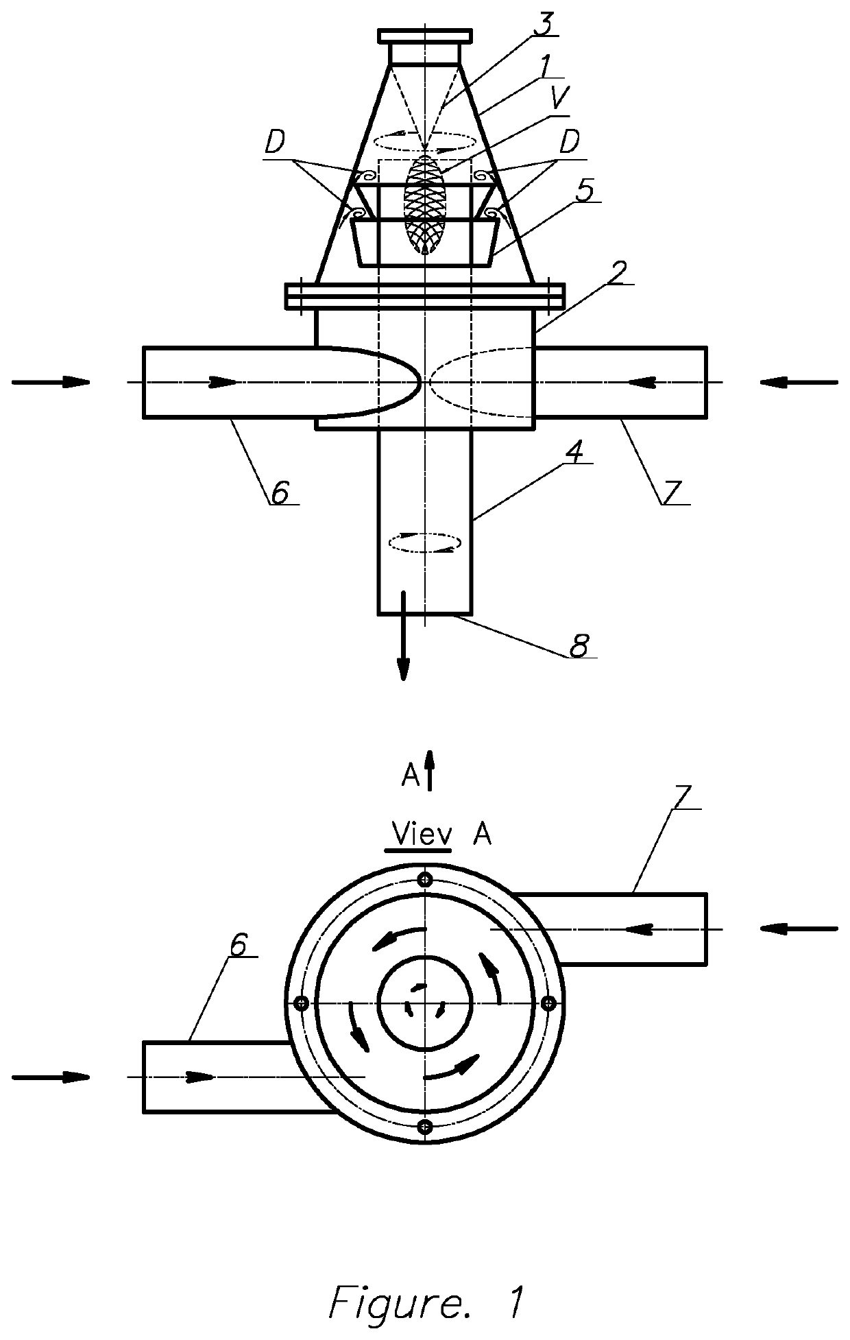
[0046]According to one preferred embodiment (FIG. 4), the inventive MHVR comprises: a housing 1 tapered upward and having curvilinear internal walls (wherein the preferable shape of the internal walls is parabola); a hollow base 2 (preferably of a cylindrical shape) attached to the bottom of housing 1; an inverse taper 3 (preferably of a conical shape) narrowing downward with its upper inner portion attached to the top of housing 1 preferably by means of a threaded joint; a supporting pipe 4 having a top inlet 10 and a bottom discharge outlet 8, and passing through the ...


PUM

PropertyMeasurementUnit
Pressureaaaaaaaaaa
Speedaaaaaaaaaa

Abstract

The proposed multifunctional hydrodynamic vortex type reactor includes—a housing having curvilinear inner sidewalls,—a base attached to the housing, an inverse taper narrowing downward and attached to the top of housing,—a supporting tube passing at least through the housing and base,—a set of washers tapered downward and mounted on an outer surface of the supporting tube such that outer upper edges of the set of washers and the inner sidewalls form predetermined gaps therebetween, and—a number of inlets tangentially attached to the base for introducing, under external pressure, a solid substance and a liquid (or a suspension of their mixture) thereinto, forming a circulating flow therein. The flow forms a high speed bypassing cavitation zone and, changing its direction at the inverse taper, forms a vortex cavitation zone, providing for mixing and grinding the substance up to nanoscale sizes. Methods for intensifying cavitation are also provided.

Description

CROSS-REFERENCES TO RELATED APPLICATIONS[0001]This U.S. patent application is a continuation-in-part application of a U.S. patent non-provisional application Ser. No. 15 / 429,380, published as US-2017-0239629-A1 (herein also referred to as “parent application”), filed on Feb. 10, 2017, entitled “Multifunctional hydrodynamic vortex reactor”, claiming the benefit of a U.S. patent provisional application Ser. No. 62 / 298,101 filed on Feb. 22, 2016, wherein the disclosure of the foregoing non-provisional application and provisional application is incorporated herein in its entirety by reference.FIELD OF THE INVENTION[0002]The present invention relates to the field of machine building technology and methods therefor, while the machines and methods can in turn be used for various industrial processes, such as:[0003]producing of fine suspensions in liquid-solid systems at production of fertilizers, biological additives, dyes, mortars, etc.;[0004]producing of fine emulsions and solutions in l...

Claims


Application Information

Patent Timeline
IPC IPC(8): B01F5/00B01F3/12B01F11/02B01F13/10B02C19/06B02C23/36
CPCB01F11/0283B02C23/36B01F3/1242B01F5/0057B01F13/1041B02C19/061B01F23/41B01F23/50B01F25/1042B01F25/10B01F23/551B01F31/87B01F33/83
Inventor GALAKA, OLEKSANDRKOZLOVSKYI, OLEKSANDRMATVIENKO, YURII
Owner GALAKA OLEKSANDR
Why Eureka
Try Eureka