High-resolution ratio moon edge optical imaging objective lens

An optical imaging, high-resolution technology, applied in the field of optical systems, can solve the problems of difficult design and processing, small optical aberration, high pointing accuracy, etc., to reduce the difficulty of procurement and manufacturing costs, reduce the pressure of aberration correction, and facilitate processing The effect of harmony

Active Publication Date: 2016-03-30
CHANGCHUN INST OF OPTICS FINE MECHANICS & PHYSICS CHINESE ACAD OF SCI
View PDF4 Cites 2 Cited by
  • Summary
  • Abstract
  • Description
  • Claims
  • Application Information

AI Technical Summary

Problems solved by technology

The traditional attitude determination using the combination of star sensor and gyroscope requires the computer on the ground and the satellite to provide accurate orbit information. The satellite attitude determination accuracy is very dependent on the orbit determination accuracy, and the single attitude determination takes a long time.
At the same time, when the star sensor on the near-orbit satellite around the moon images the moon, the optical system needs a field of view of 100° to 150° to cover the entire moon. For a single transmission imaging lens, small optical aberrations and high The pointing accuracy is relatively difficult in design and post-processing, and requires the use of aspheric lens structures, special lens materials, etc., resulting in high manufacturing and testing costs for optical system parts and complete machines, and uncertain working stability in space environments

Method used


Image

  • High-resolution ratio moon edge optical imaging objective lens
  • High-resolution ratio moon edge optical imaging objective lens
  • High-resolution ratio moon edge optical imaging objective lens

Examples


Embodiment Construction

[0027] The present invention will be described in further detail below in conjunction with the accompanying drawings.

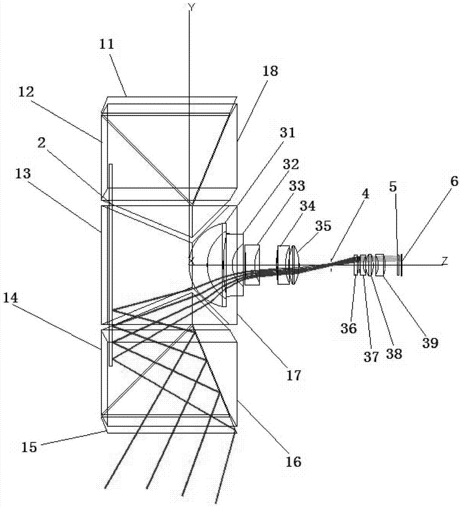
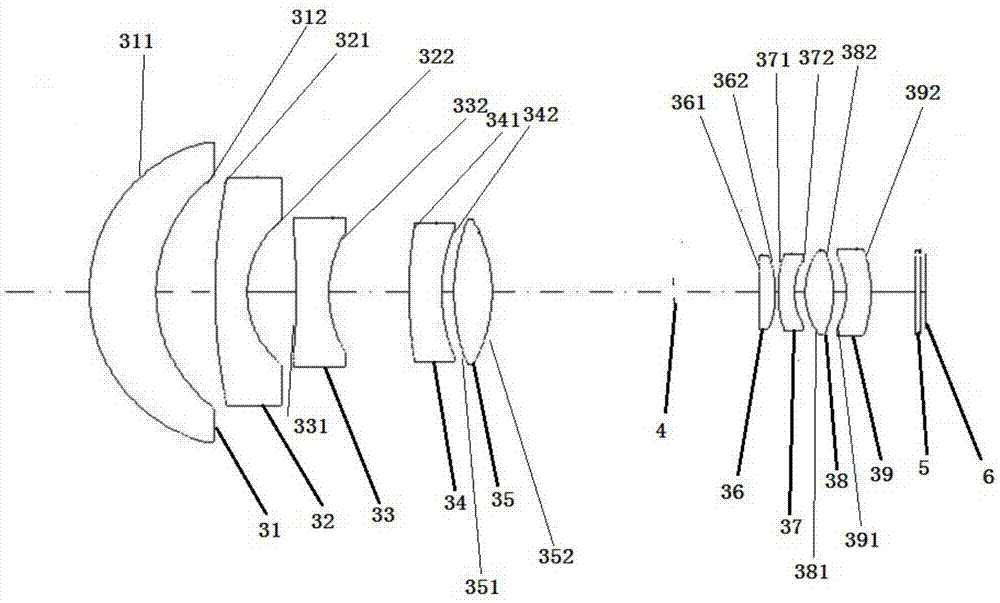
[0028] Such as figure 1 As shown, a high-resolution lunar edge optical imaging objective lens is coaxially arranged with an isosceles Dawei reflective prism group 1, a plane reflector 2, an imaging lens group 3, a diaphragm 4, a detector protection glass 5 and The detector 6 and the plane reflector 2 are located at the front end of the isosceles Dove reflecting prism group 1 .

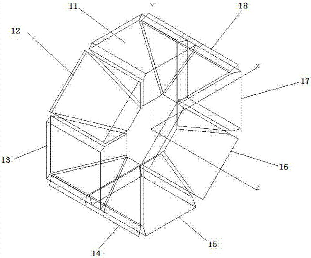
[0029] Such as figure 2 As shown, the isosceles Dawe reflective prism group 1 includes uniformly distributed circumferentially around the Z axis: the first isosceles Dawe reflector 11, the second isosceles Dawe reflector 12, and the third isosceles Dawe reflector Prism 13, the fourth isosceles Dawe reflection prism 14, the fifth isosceles Dawe reflection prism 15, the sixth isosceles Dawe reflection prism 16, the seventh isosceles Dawe reflection prism 17, the eighth isosceles Dawe...


PUM


Abstract

The invention discloses a high-resolution ratio moon edge optical imaging objective lens belonging to the optical system technology field. In order to solve the problems of the prior art, the objective lens is provided with an isosceles Dove reflecting prism group, a plane reflecting mirror, an imaging lens group, a diaphragm, a piece of detector protection glass, and a detector, which are coaxially arranged according to the light incoming sequence. The plane reflecting mirror is disposed on the front end of the isosceles Dove reflecting prism group. The isosceles Dove reflecting prism group comprises eight isosceles Dove reflecting prisms, which are uniformly arranged around a Z axis in a peripheral direction. The incoming light can transmit through the lower surface of each isosceles Dove reflecting prism of the isosceles Dove reflecting prism group. For each of the isosceles Dove reflecting prisms, the incoming light can be reflected by one isosceles surface, and can transmit through the other isosceles surface, and then can be reflected by the plane reflecting mirror, and then the reflected light can transmit through the imaging lens group and the detector protection glass sequentially, and then can be received by the detector. The high-resolution ratio moon edge optical imaging objective lens can be used to satisfy the high precision attitude determination requirement of the circumlunar satellite.

Description

technical field [0001] The invention relates to a high-resolution lunar edge optical imaging objective lens, which belongs to the technical field of optical systems. Background technique [0002] Satellites flying around the moon need to determine their own pitch and roll attitude in real time. The traditional attitude determination using the combination of star sensor and gyroscope requires the computer on the ground and the satellite to provide accurate orbit information. The accuracy of satellite attitude determination is very dependent on the accuracy of orbit determination, and the single attitude determination takes a long time. At the same time, when the star sensor on the near-orbit satellite around the moon images the moon, the optical system needs a field of view of 100° to 150° to cover the entire moon. For a single transmission imaging lens, small optical aberrations and high The pointing accuracy is relatively difficult in design and post-processing, and requir...

Claims


Application Information

Patent Timeline
Patent Type & Authority Applications(China)
IPC IPC(8): G02B27/00G02B13/00G02B1/00
CPCG02B1/00G02B13/0065G02B27/0025
Inventor 吕博姜珊冯睿张大亮魏忠伦付瀚毅刘伟奇
Owner CHANGCHUN INST OF OPTICS FINE MECHANICS & PHYSICS CHINESE ACAD OF SCI
Why Eureka
Try Eureka