Laser beam splitter

A laser beam splitter and laser technology, applied in optics, instruments, optical components, etc., can solve the problems of difficult processing, large vector, etc., and achieve the effects of easy fabrication, shallow processing depth, and overcoming the limitation of feature size.

Pending Publication Date: 2019-04-16
ZHUHAI MULTISCALE PHOTOELECTRIC TECH CO LTD
View PDF0 Cites 5 Cited by
  • Summary
  • Abstract
  • Description
  • Claims
  • Application Information

AI Technical Summary

Problems solved by technology

[0003] In view of this, it is necessary to address the defects of the existing technology and provide a laser beam splitter that can solve the problem of difficult processing caused by the large vector height of the existing microlens array beam splitter based on continuous curved surfaces

Method used


Image

  • Laser beam splitter
  • Laser beam splitter
  • Laser beam splitter

Examples


Embodiment 1

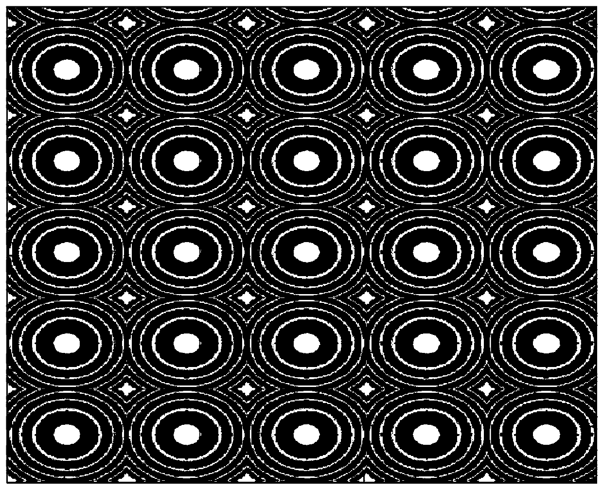
[0032] see figure 1 , is a schematic structural diagram of the laser beam splitter provided in Embodiment 1 of the present invention.

[0033] In this embodiment, the internal structure of the laser beam splitter is a Fresnel periodic array, and the array period is 6 microns; the structure and array arrangement of the Fresnel periodic array are figure 1 The rectangular arrangement is shown; the Fresnel periodic array is obtained by the corresponding microlens through 2π phase folding; when the laser wavelength is 830nm, the far-field beam splitting lattice generated at a distance of 100mm is as follows Figure 5 As shown, the energy distribution of the beam splitting lattice is uniform, there is no central zero order with obvious brightness difference, and the lattice satisfies the rectangular arrangement.

Embodiment 2

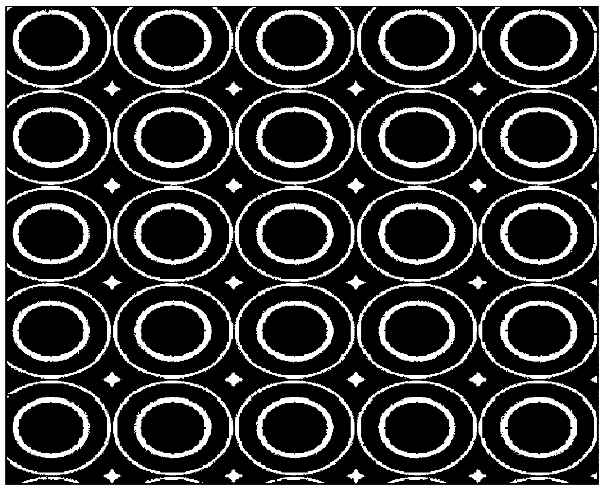
[0035] see figure 2 , is a schematic structural diagram of the laser beam splitter provided by Embodiment 2 of the present invention.

[0036] In this embodiment, the internal structure of the laser beam splitter is a Fresnel ring array, and the array period is 6 microns; the structure and array arrangement of the Fresnel ring array are figure 2 The rectangular arrangement shown; the Fresnel ring array is obtained by the corresponding microlens through 4π phase folding; at the laser wavelength of 830nm, the far-field beam splitting lattice generated at a distance of 100mm is as follows Figure 5 As shown, the energy distribution of the beam splitting lattice is uniform, there is no central zero order with obvious brightness difference, and the lattice satisfies the rectangular arrangement.

Embodiment 3

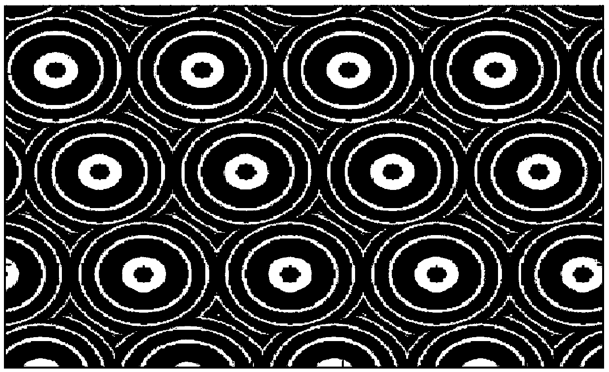
[0038] see image 3 , is a schematic structural diagram of the laser beam splitter provided by Embodiment 3 of the present invention.

[0039] In this embodiment, the internal structure of the laser beam splitter is a Fresnel ring array, and the array period is 8 microns; the structure and array arrangement of the Fresnel ring array are image 3 The rhombus dislocation arrangement is shown; the Fresnel ring array is obtained by 2π phase folding for the corresponding microlens; at the laser wavelength of 940nm, the far-field beam splitting lattice generated at a distance of 300mm is as follows Image 6 As shown, the energy distribution of the beam-splitting lattice is uniform, there is no central zero order with obvious brightness difference, and the lattice satisfies the dislocation arrangement.


PUM


Abstract

A laser beam splitter provided in the invention is formed by Fresnel rings arranged in an array. The vector height of a three-dimensional curved surface micro lens is reduced through Fresnel folding,a processing depth is shallow and a making process is easy. The laser beam splitter can acquire a same diffraction effect with that of a three-dimensional curved surface micro lens array, which meansthat a beam splitting pattern with a large angle and good uniformity is generated in a far field, and a beam splitting angle is not limited by a characteristic size. A problem that the beam splittingangle of a traditional binary diffraction beam splitter is limited by the characteristic size is overcome.

Description

technical field [0001] The invention relates to the technical field of optical devices, in particular to a laser beam splitter. Background technique [0002] Laser beam splitters are widely used in laser processing, three-dimensional measurement, optical alignment, optical communication, and lighting display. Traditional laser beam splitters use binary optics to obtain laser beam splitting patterns through special step-type phase modulation. However, the beam splitting pattern angle of this diffractive beam splitter is limited by the lateral feature size of the step, and it is difficult to process large-angle beam splitting; secondly, a small error in the step depth will cause the beam splitter to generate much higher energy than other levels. The secondary central zero-order spot leads to uneven energy distribution of the beam splitting lattice, and its use is limited. In order to solve the above problems, a new type of microlens array beam splitter based on continuous cu...

Claims


Application Information

Patent Timeline
Patent Type & Authority Applications(China)
IPC IPC(8): G02B27/12
CPCG02B27/123
Inventor 夏良平王乡杜春雷
Owner ZHUHAI MULTISCALE PHOTOELECTRIC TECH CO LTD
Why Eureka
Try Eureka