
Vacuum Cleaner Device

a vacuum cleaner and vacuum cleaner technology, applied in the direction of suction cleaners, cleaning equipment, electric equipment installation, etc., can solve the problems of difficult application of sensors, limited durability of relative humidity sensors, and negative slope of sampled relative humidity, so as to achieve less mechanical damage

Active Publication Date: 2020-03-05
SENSIRION AG
View PDF0 Cites 4 Cited by
  • Summary
  • Abstract
  • Description
  • Claims
  • Application Information

AI Technical Summary

Benefits of technology

The patent text describes how a temperature sensor can be used to detect wet spots on a floor more accurately and with fewer false signals. This is because the sensor is located on the device in a more shielded area, which reduces the likelihood of damage. Additionally, the text suggests that the sensor can be placed in the suction duct after a filter to protect it from contamination and damage. The detection of wet spots using a temperature sensor is important because it can help improve the reliability and durability of the device.

Problems solved by technology

Regarding the use of relative humidity sensors it turns out that these sensors are rather difficult to apply to the task of detecting individual wet spots on a floor area on which the vacuum cleaner device operates, since such sensors are usually rather slow and can therefore be inaccurate in the detection of a wet spot.
Also the durability of an relative humidity sensor can be limited since these sensors are usually prone to dust.
Furthermore, when leaving the wet spot, the slope of the sampled relative humidity will be negative.

Method used


Image

  • Vacuum Cleaner Device
  • Vacuum Cleaner Device
  • Vacuum Cleaner Device

Examples


Embodiment Construction

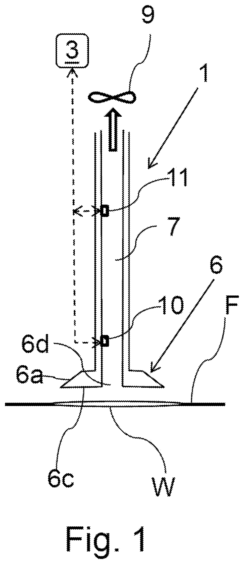
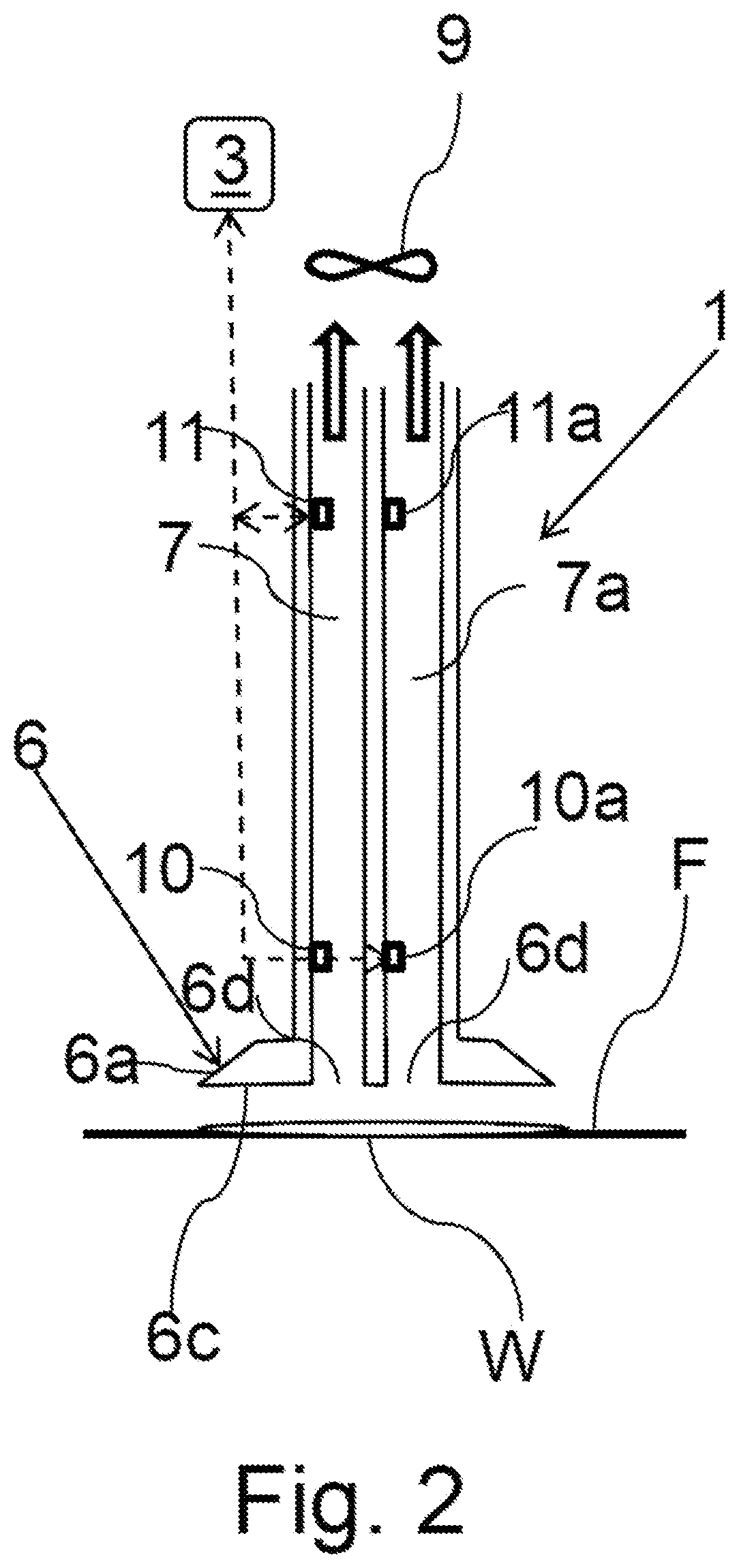
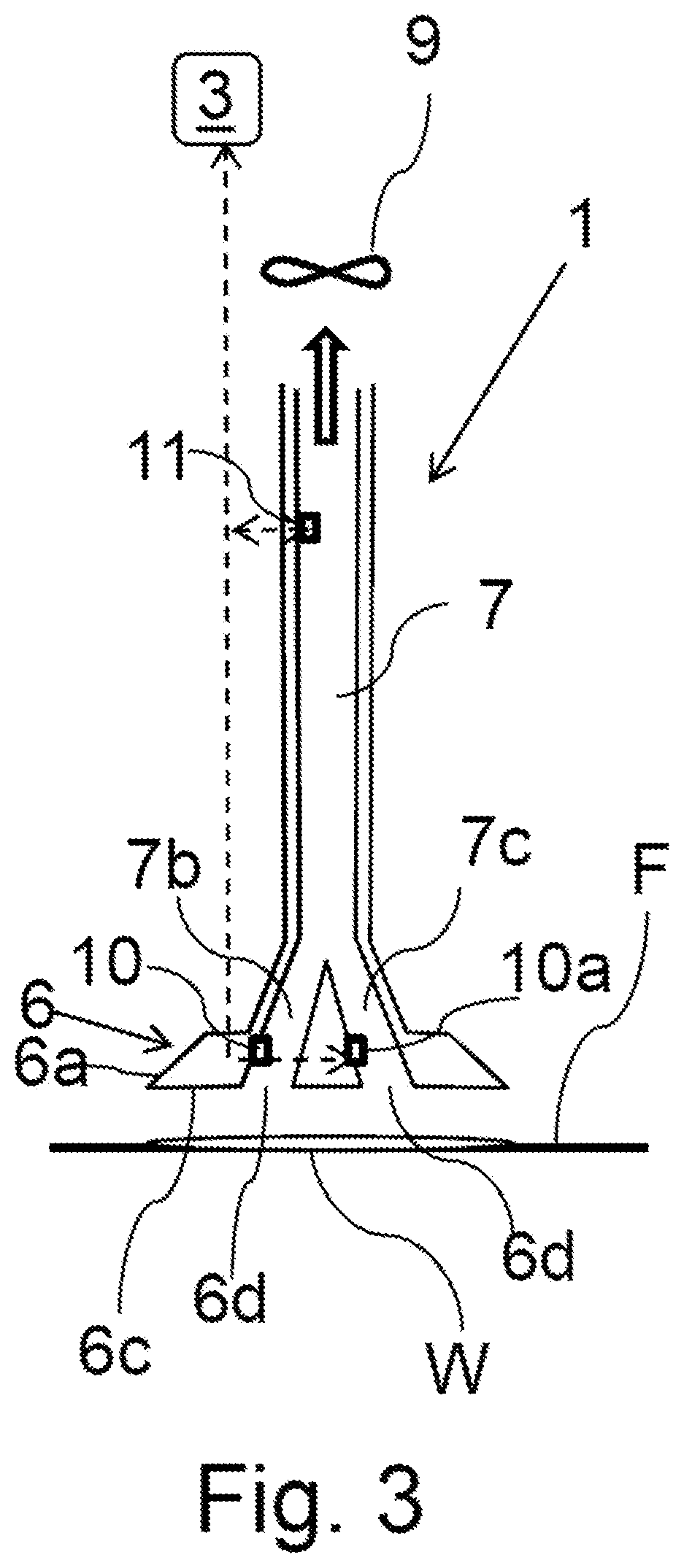
[0085]FIG. 1 shows a vacuum cleaner device 1 for operation on a floor area F, wherein the device 1 comprises a suction duct 7 and an actuator 9 (e.g. a ventilator) that is configured to generate an underpressure in the suction duct 7 so that air is sucked into the suction duct 7. Further, the device 1 comprises a temperature sensor 10 configured to sample an air temperature in the vicinity of the device 1, wherein said temperature sensor 10 is arranged in the suction duct 7. Furthermore, the vacuum cleaner device 1 comprises an analyzing unit 3 configured to detect a wet spot W on said floor area F using said sampled air temperature.

[0086]Particularly, the device 1 comprise a head 6 having a bottom wall 6c configured to face said floor area F upon operation of the device 1 on said floor area F. Further, the head 6 may comprise a circumferential lateral wall 6a extending from the bottom wall 6c.

[0087]Alternatively, instead of arranging the temperature sensor 10 in the suction duct 7...


PUM


Abstract

The present invention relates to a vacuum cleaner device (1) for operation on a floor area (F), comprising: a suction duct (7) and an actuator (9) arranged and configured to generate an underpressure in the suction duct (7) so that air is sucked into the suction duct (7), a temperature sensor (10) configured to sample an air temperature in the vicinity of the device (1), wherein said temperature sensor (10) is arranged in the suction duct (7) or adjacent an opening (6d) of the suction duct (7), and an analyzing unit (3) configured to detect a wet spot (W) on said floor area (F) using said sampled air temperature.

Description

TECHNICAL FIELD AND BACKGROUND[0001]The present invention relates to a vacuum cleaner device.[0002]Such a vacuum cleaner device can be used, e.g. in a household, for vacuum cleaning, sweeping (wet-vac) etc.[0003]During operation of such devices it is usually desirable to detect wet spots (e.g. liquid layers, e.g. due to a spilled liquid) on the floor area (e.g. a carpet or a hard floor) so that the device does not suck up the liquid (in case the vacuum cleaner device is not configured for removing liquids) or repeatedly moves over the wet spot. Further, in case a wet spot is detected, the owner / user can be alerted about the presence of liquids. Such features are especially useful for autonomous operation of robotic vacuum cleaner devices.[0004]In the prior art it is known to use relative humidity sensors to determine wet spots (e.g. US2006130646A1) or to avoid double cleaning (e.g. WO2008 / 007830A1). Furthermore, the device disclosed in US2016066759A1 comprises a temperature sensor, ...

Claims


Application Information

Patent Timeline
Patent Type & Authority Applications(United States)
IPC IPC(8): A47L9/28
CPCA47L9/2826A47L2201/06
Inventor EICHBERGER, MAXIMILIANZIMMERMANN, BERND
Owner SENSIRION AG
Learn More