Vent control valve for fuel tank

Active Publication Date: 2020-03-12
KYOSAN DENKI KABUSHIKI KAISHA
View PDF14 Cites 0 Cited by
  • Summary
  • Abstract
  • Description
  • Claims
  • Application Information

AI Technical Summary

Benefits of technology

[0008]It is another object of the present disclosure to provide a vent control valve fo

Problems solved by technology

However, if the additional case drops off on the lower sid

Method used


Image

  • Vent control valve for fuel tank
  • Vent control valve for fuel tank
  • Vent control valve for fuel tank

Examples


first embodiment

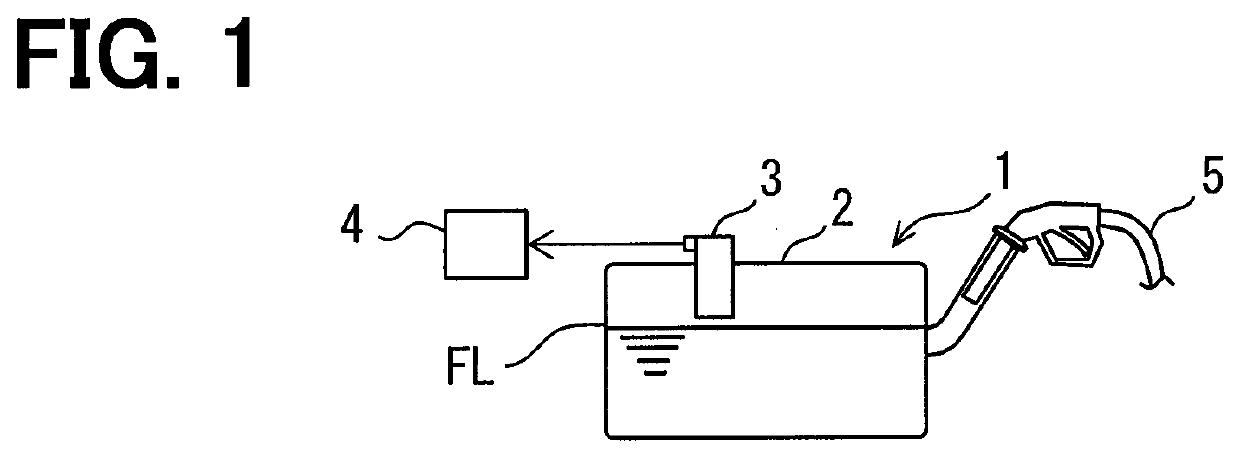
[0019]As shown in FIG. 1, a fuel storage equipment 1 includes a fuel tank 2, a fuel supply control valve 3, and a fuel evaporation processing unit 4. The fuel storage equipment 1 is disposed in a vehicle. The fuel storage equipment 1 may include a fuel supply device which supplies fuel to an internal-combustion engine of the vehicle.

[0020]The fuel supply control valve 3 is arranged in the fuel tank 2. The fuel supply control valve 3 may be arranged in the fuel supply device such as pump module in the fuel tank 2. The fuel supply control valve 3 provides a float valve for the fuel tank. The fuel supply control valve 3 controls a ventilation between the fuel tank 2 and the exterior. The fuel supply control valve 3 is arranged in a vent passage for ventilation between the fuel tank 2 and the fuel evaporation processing unit 4. The vent passage is used for discharge gas from the fuel tank 2 to the fuel evaporation processing unit 4. The vent passage is also called as a ventilation passa...


PUM


Abstract

A vent control valve includes: a first case shaped in a tube that forms a passage for ventilation; a movable valve object arranged in the first case to open and close the passage; an inner case arranged in the first case to support the movable valve object; a second case disposed at a lower end of the first case; a first connection mechanism defined between the first case and the inner case, the first connection mechanism connecting the first case and the inner case with each other; and a second connection mechanism defined between the first case and the second case, the second connection mechanism connecting the first case and the second case with each other.

Description

CROSS REFERENCE TO RELATED APPLICATION[0001]This application is based on Japanese Patent Application No. 2015-208310 filed on Oct. 22, 2015, the disclosure of which is incorporated herein by reference.TECHNICAL FIELD[0002]The present disclosure relates to a vent control valve that opens and closes a vent passage of a fuel tank.BACKGROUND ART[0003]Each of Patent Literature 1 and Patent Literature 2 discloses a float valve disposed in a vent passage of a fuel tank. The float valve is applied as a fuel supply control valve in the disclosure. The fuel supply control valve may be also called as a full control valve that controls the fuel supply to make the fuel tank full (where the fuel is supplied to the maximum of the fuel tank). This equipment controls the passage of fuel evaporated in the fuel tank to stop a fueling device. This equipment is equipped with two valves for controlling the passage. This equipment has a float valve that is closed to stop the passage by floating in liquid ...

Claims


Application Information

Patent Timeline
IPC IPC(8): B60K15/035F16K24/04
CPCF16K24/046B60K15/03519B60K15/035B60K2015/03289B60K2015/03557B60K2015/03576F16K17/196F16K24/04F16K31/22F02M37/00F16K24/042Y10T137/0874Y10T137/3099
Inventor MUKASA, YUSUKEMUTO, NOBUHARU
Owner KYOSAN DENKI KABUSHIKI KAISHA
Why Eureka
Try Eureka