
Evaporated fuel treatment device and fluid treatment device

Active Publication Date: 2021-08-26
HONDA MOTOR CO LTD
View PDF0 Cites 1 Cited by
  • Summary
  • Abstract
  • Description
  • Claims
  • Application Information

AI Technical Summary

Benefits of technology

The present invention provides an evaporated fuel treatment device and a fluid treatment device that can quickly and easily inspect the negative pressure generation function without releasing evaporated fuel to the atmosphere. The device includes a purge pump that can be easily removed from the pump mounting part without causing any negative pressure loss. A through hole is formed in the purge pump to connect the pump flow path with the second introduction part, and the pump mounting part is in close contact with an annular seal surface, which simplifies the connection flow path. These technical effects enable efficient inspection of the negative pressure generation function and prevention of evaporated fuel release.

Problems solved by technology

That is, the jet pump described in Patent Document 1 cannot be inspected for the quality of the negative pressure generation function by itself.
Furthermore, for performing the inspection, it is necessary to assemble the jet pump, which takes time and labor.

Method used


Image

  • Evaporated fuel treatment device and fluid treatment device
  • Evaporated fuel treatment device and fluid treatment device
  • Evaporated fuel treatment device and fluid treatment device

Examples


Embodiment Construction

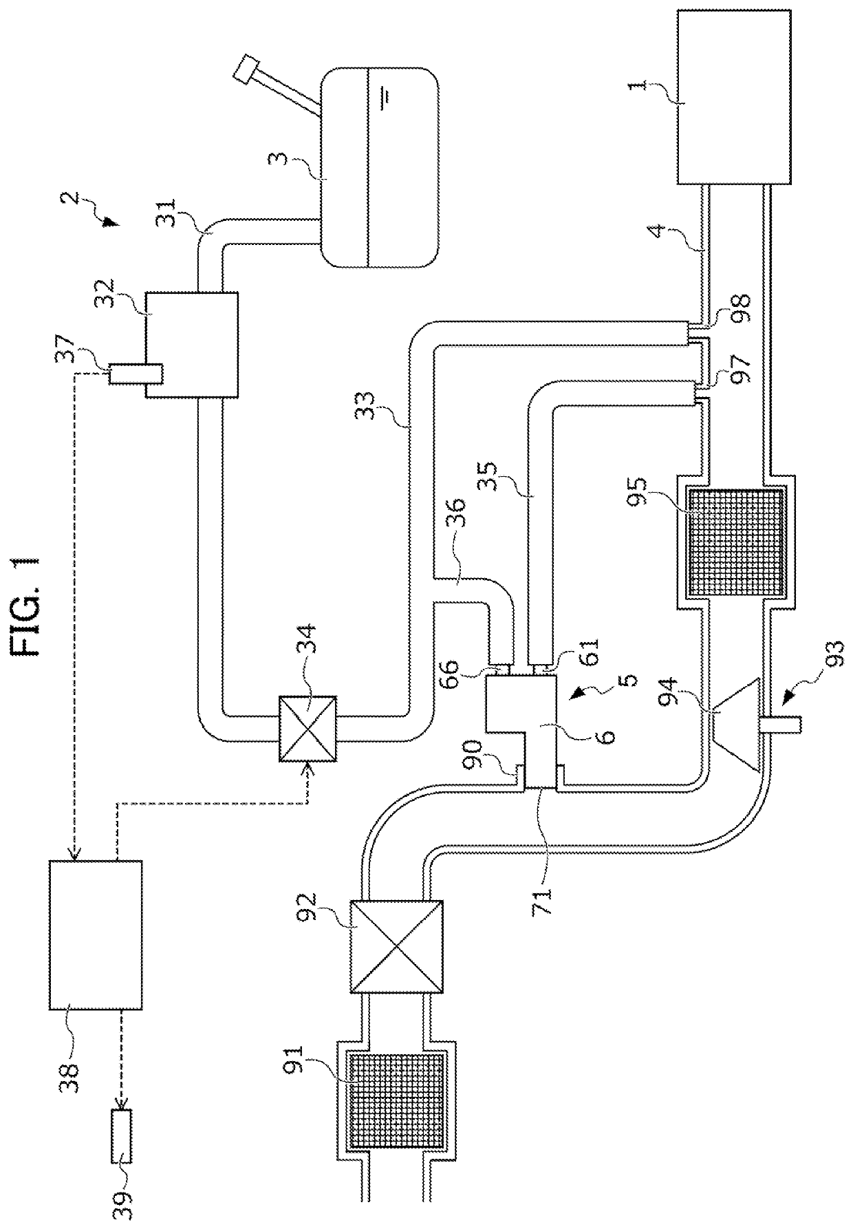
[0030]Hereinafter, an embodiment of the present invention will be described with reference to the drawings. FIG. 1 is a view schematically showing a configuration including an evaporated fuel treatment device 2 according to the present embodiment and an intake system of an internal combustion engine (hereinafter, referred to simply as “an engine”) 1 to which this evaporated fuel treatment device 2 is applied.

[0031]In an intake pipe 4 that supplies air to unshown respective cylinders of the engine 1, an air cleaner 91 that removes foreign matter from air, an air flowmeter 92 that generates a signal in accordance with a flow rate of air to be introduced to each cylinder via the intake pipe 4, a compressor 94 of a supercharger 93 that compresses intake air by use of energy of exhaust of the engine 1 and an intercooler 95 that cools the intake air are provided in order from an upstream side toward a downstream side.

[0032]A pump mounting part 90 to which a pump body 6 of an after-mention...


PUM


Abstract

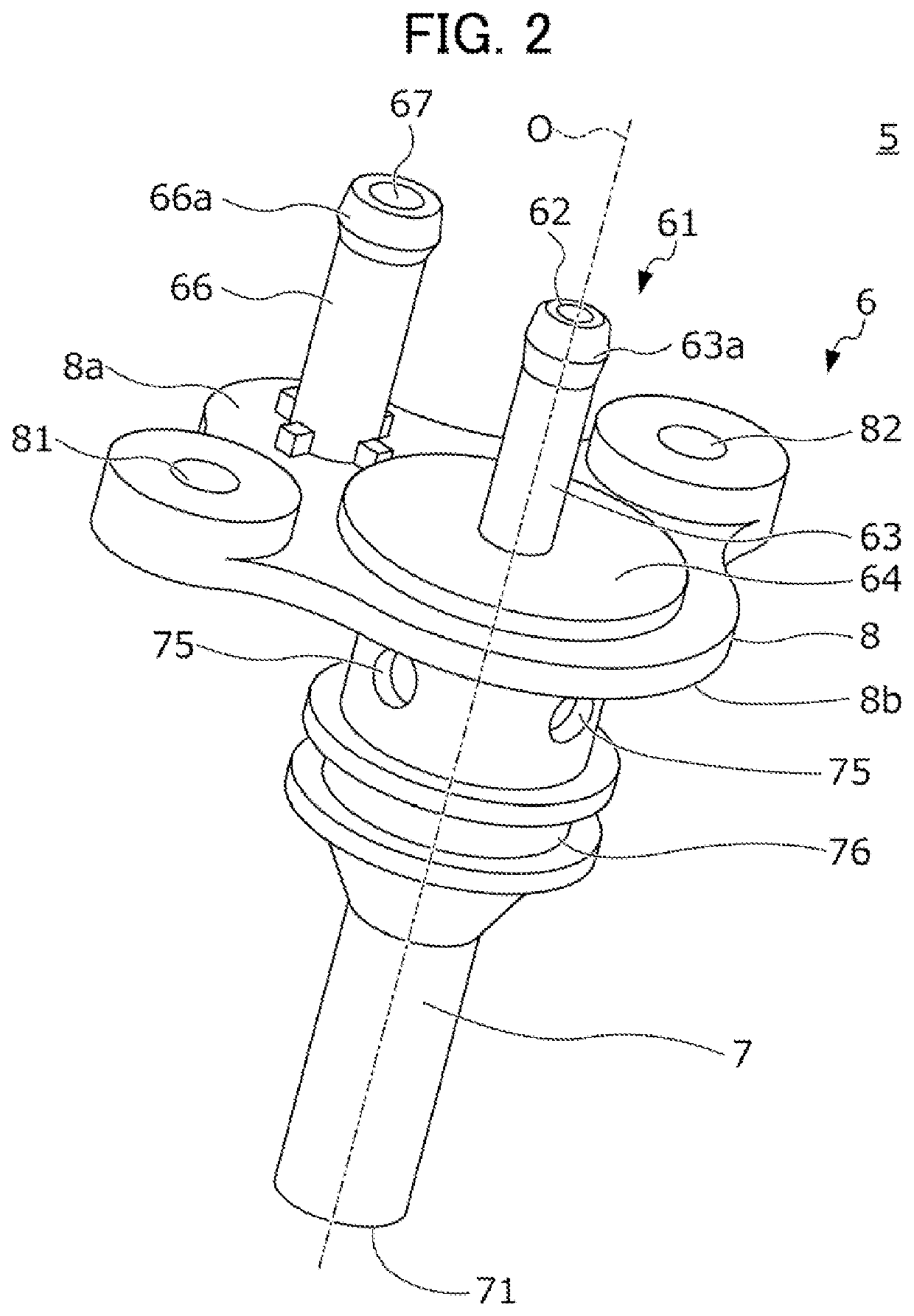
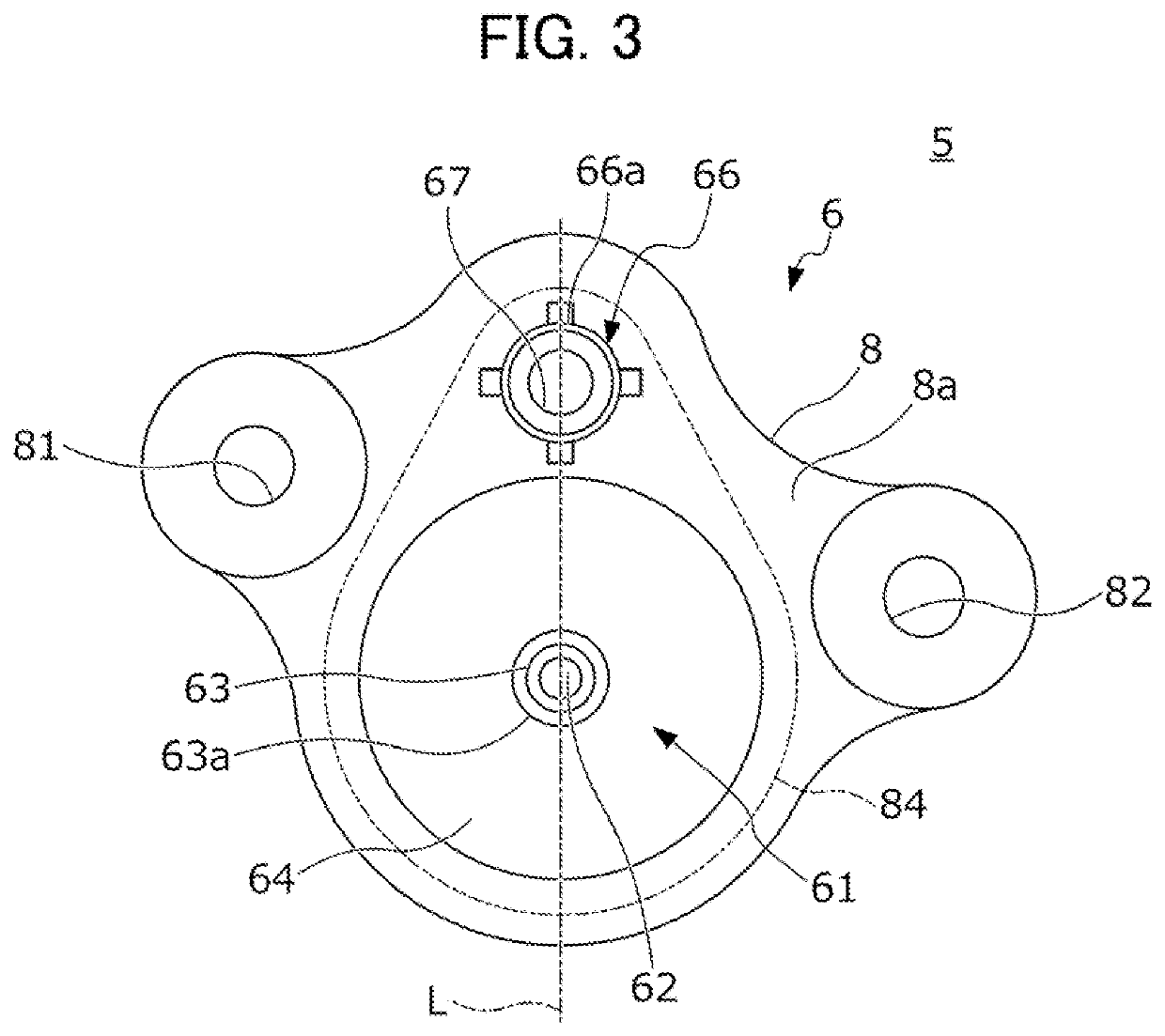
Provided is an evaporated fuel treatment device including a mounting part 90 provided in an intake pipe, and a purge pump 5 including a discharge part 71, a first introduction tube 61, and a second introduction tube 66. A pump body 6 of the purge pump 5 includes a pump tube 7 formed with a pump flow path 70 that extends along an axis O and that guides, to the discharge part 71, fluid to be introduced from the introduction tube 61. A reduced part 73 with a diameter decreasing toward downstream is formed in the flow path 70 on a side downstream of the introduction tube 61, and a connection flow path 78 that connects the introduction tube 66 and the flow path 70 is formed, and in a state where the pump body 6 is removed from the mounting part 90, the flow path 78 communicates with outside.

Description

[0001]This application is based on and claims the benefit of priority from Japanese Patent Application No. 2020-030625, filed on 26 Feb. 2020, the content of which is incorporated herein by reference.BACKGROUND OF THE INVENTIONField of the Invention[0002]The present invention relates to an evaporated fuel treatment device and a fluid treatment device.Related Art[0003]In a vehicle comprising a fuel tank, an evaporated fuel treatment device that treats evaporated fuel generated in this fuel tank is mounted. In a conventional evaporated fuel treatment device, the evaporated fuel generated in the fuel tank is adsorbed on activated carbon in a canister, and the evaporated fuel adsorbed on the activated carbon is purged with fresh air by use of negative pressure generated in an intake pipe, to be introduced into the intake pipe and combusted in an engine. In a case where the intake pipe is provided with a supercharger compressor, however, during supercharging, the intake pipe has positive...

Claims


Application Information

Patent Timeline
IPC IPC(8): F02M25/08
CPCF02M25/089F02M25/0872F02M25/08F02M25/0854Y02T10/12
Inventor KAWANISHI, HIROSHIISHII, NAOAKI
Owner HONDA MOTOR CO LTD
Learn More