Cartridge

Active Publication Date: 2005-11-15
FUJIFILM CORP +1
View PDF8 Cites 2 Cited by
  • Summary
  • Abstract
  • Description
  • Claims
  • Application Information

AI Technical Summary

Benefits of technology

[0009]In consideration of the circumstances described above, an object of the present invention is to provide a cartridge at which peeling off of a label that has been adhered to a label area is easy, while a function of positioning the label at the label area is maintained.
[0011]At the cartridge described above, because the cut-away portion which is continuous with the label area is provided, by excising the standing wall surrounding the label area (defining outer edges of the label area), a label that has been adhered to the label area can be easily peeled from the case.
[0012]The cut-away portion is formed at a portion in the longitudinal direction in one of the side portions of the standing wall. That is, the one side portion is not excised and opened up across the whole length thereof. Thus, the rectangular label area is enclosed from four sides by the standing wall. In consequence, a label can be accurately positioned in the label area.
[0013]Thus, with this cartridge, peeling off of a label that has been adhered to the label area is easy, while the function of positioning the label at the label area is maintained.
[0015]The cut-away portion may be excised and provided at a central portion of an upper side portion of the standing wall surrounding the label area (a long side portion of the label area provided at the rear wall). Therefore, the cut-away portion can be specified to be relatively large, and the cut-away portion can be distanced from corner portions of the label (portions which are susceptible to peeling). Thus, with this cartridge, ease of peeling of the label is improved, but unintended peeling off of the label is prevented.
[0016]The cut-away portion of the case may be provided to be continuous with an upper face of the case. That is, the cut-away portion opens to upward of the case. Hence, an upper end (thickness portion) of a label adhered to the label area is exposed upward through the cut-away portion. Thus, with this cartridge, peeling off of a label which has been adhered to the label area is even easier.

Problems solved by technology

Consequently, there is a problem in that labels that have been adhered are difficult to peel off.
However, when the label area is enlarged, positioning accuracy of the label deteriorates.
Moreover, because the label area is a thin wall portion of the case, enlarging the label area is not preferable with regard to strength.
Furthermore, a label area which is provided at a rear face side of a case is generally formed to span substantially the whole of the rear face, and there is very little free space available for enlargement.

Method used


Image

  • Cartridge
  • Cartridge
  • Cartridge

Examples


Embodiment Construction

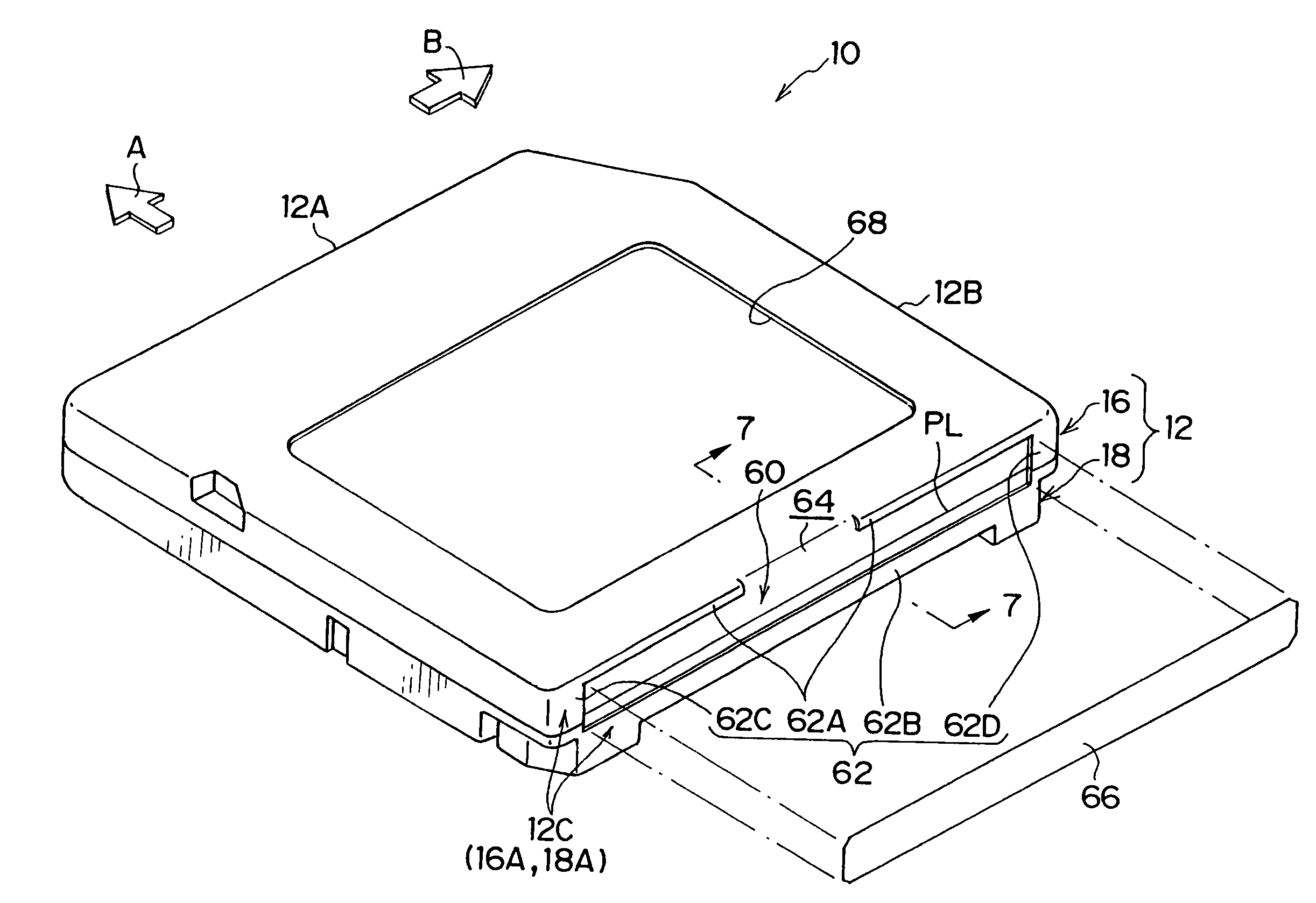
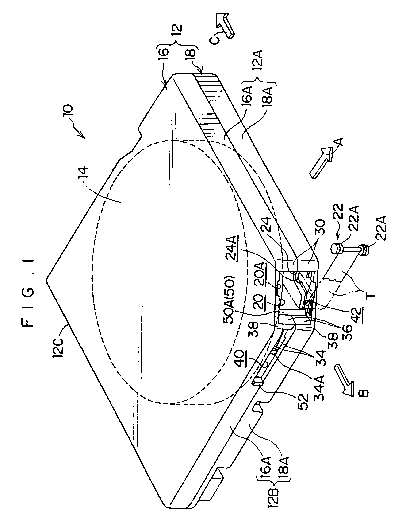
[0027]A recording tape cartridge 10 relating to an embodiment of the present invention will be described on the basis of FIGS. 1 to 7. First, general overall structure of the recording tape cartridge 10 and structures of an opening and a door will be described. Thereafter, a label area 60, which is a principal element of the present invention, will be described. For the sake of convenience of explanation, a loading direction of the recording tape cartridge 10 into a drive device, which is shown by arrow A, is taken to be a forward direction (front side) of the recording tape cartridge 10, and the direction of an arrow B, which intersects arrow A, is taken to be a rightward direction.

Overall Structure of Recording Tape Cartridge

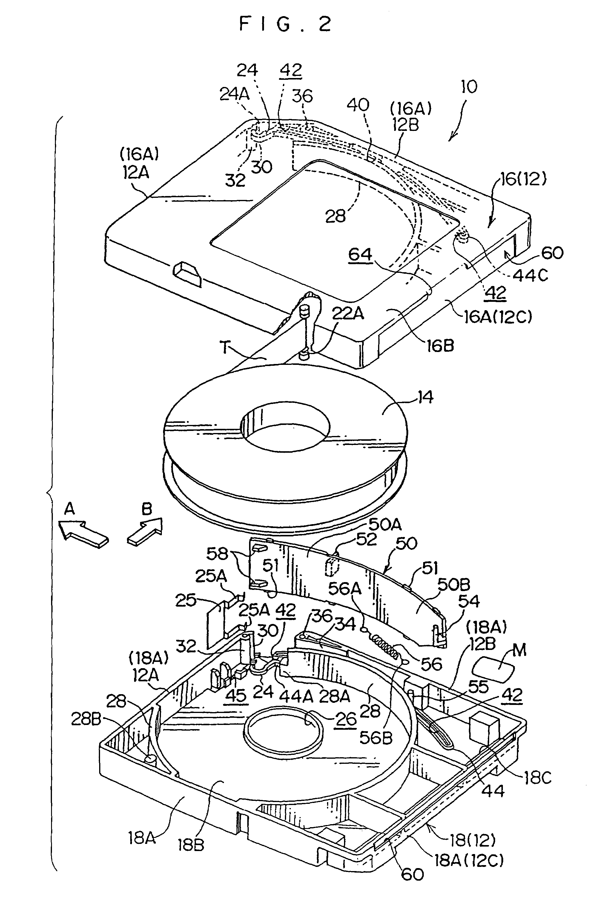
[0028]A perspective view of the overall structure of the recording tape cartridge 10 is shown in FIG. 1 and, a schematic exploded perspective view of the recording tape cartridge 10 is shown in FIG. 2.

[0029]As shown in FIGS. 1 and 2, the recording tape cartrid...


PUM


Abstract

A cartridge is provided with a case, which accommodates a recording medium at an interior thereof, and a label area, which is surrounded by a rectangular standing wall at an outer face of the case. At one side of the standing wall, a longitudinal direction portion is cut away. Thus, a cut-away portion which is continuous with the label area is provided. The label area is formed at a rear wall, at a rear side in a direction of loading the case into a drive device. The cut-away portion is formed at a substantially central portion, in a longitudinal direction, of an upper side of the standing wall.

Description

CROSS-REFERENCE TO RELATED APPLICATION[0001]This application claims priority under 35 USC 119 from Japanese Patent Application No. 2002-255108, the disclosure of which is incorporated by reference herein.BACKGROUND OF THE INVENTION[0002]1. Field of the Invention[0003]The present invention relates to a cartridge which accommodates a recording medium in a case and is provided with a write-protect function which switches between a state in which recording of information to the recording medium is enabled and a state in which recording is disabled.[0004]2. Brief Description of the Related Art[0005]Cartridges which accommodate recording media in cases are used as external recording media for computers and the like. Specifically, a cartridge has a structure in which a recording medium, such as a recording tape wound on a reel, a disc-form disc medium or the like, is rotatably accommodated in a case which has been formed to be hollow by matching peripheral walls of an upper case and a lowe...

Claims


Application Information

Patent Timeline
IPC IPC(8): G11B23/107G11B23/04G11B23/08G11B23/38
CPCG11B23/045G11B23/046G11B23/107
Inventor IINO, WATARU
Owner FUJIFILM CORP
Why Eureka
Try Eureka