Surge protective device

Inactive Publication Date: 2018-12-13
MITSUBISHI MATERIALS CORP
View PDF4 Cites 0 Cited by
  • Summary
  • Abstract
  • Description
  • Claims
  • Application Information

AI Technical Summary

Benefits of technology

The present invention provides a surge protective device that can maintain its performance even when the size of a surge current or the number of discharges increases. This is achieved by including discharge-assisting parts composed of insulating layers and ion-source layers that can sublimate and disappear due to discharge, allowing the next ion-source layer to be exposed and maintaining the discharge assisting function. The surge protective device is suitable for power source and communication equipment for infrastructure where tolerance to a large current surge is required.

Problems solved by technology

The connecting parts of telephones, facsimile machines, and electronic devices for communication equipment such as a modem to communication lines, and power lines, antenna, as well as image display driving circuits for CRTs, liquid crystal display TVs, plasma display TVs, and the like are vulnerable to electric shocks such as abnormal voltage (surge voltage) due to a lightning surge or an electrostatic surge.

Method used


Image

  • Surge protective device
  • Surge protective device
  • Surge protective device

Examples


first embodiment

[0025]Hereinafter, a surge protective device according to the present invention will be described with reference to FIGS. 1 and 2. In the drawings referenced in the following description, the scale of each component may be changed as appropriate so that each component is recognizable or is readily recognized.

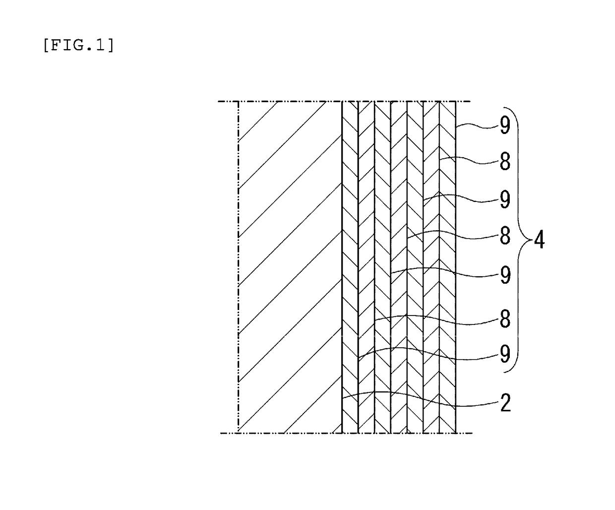
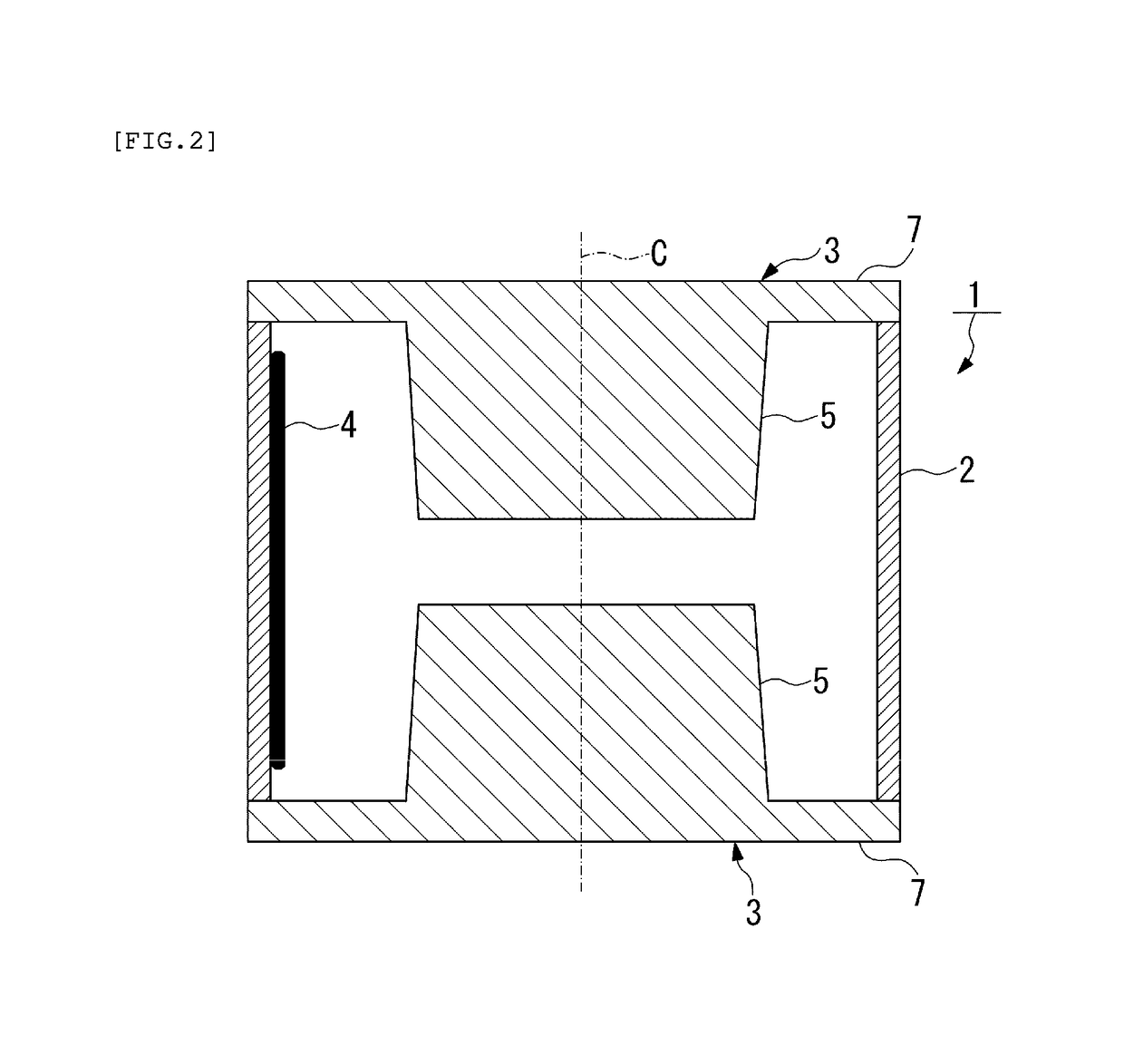
[0026]As shown in FIGS. 1 and 2, a surge protective device 1 according to the present embodiment includes an insulating tube 2, a pair of sealing electrodes 3 for closing the openings on the both ends of the insulating tube 2 so as to seal a discharge control gas inside the tube, and a discharge-assisting part 4 formed on the inner circumferential surface of the insulating tube 2.

[0027]The pair of sealing electrodes 3 have a pair of convex electrode portions 5 projecting inwardly and facing to each other.

[0028]The discharge-assisting part 4 is composed of a laminate of insulating layers 8 made of an insulating material and ion-source layers 9 made of an ion-source material that ...

second embodiment

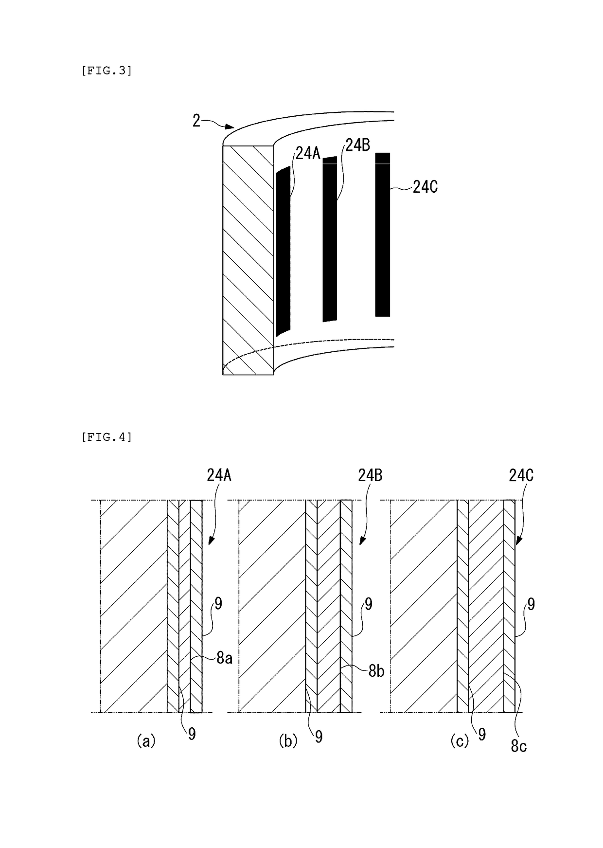
[0047]In addition, in the second embodiment, at least one of the plurality of discharge-assisting parts 24A, 24B, and 24C has the insulating layer set to have a different thickness from the others.

[0048]Specifically, in the second embodiment, the thickness of the insulating layer 8b of the discharge-assisting part 24B is larger than that of the insulating layer 8a of the discharge-assisting part 24A, and the thickness of the insulating layer 8c of the discharge-assisting part 24C is larger than that of the insulating layer 8b of the discharge-assisting part 24B.

[0049]For example, the thickness of the insulating layer 8a of the discharge-assisting part 24A is set to be 100 μm, the thickness of the insulating layer 8b of the discharge-assisting part 24B is set to be 150 μm, and the thickness of the insulating layer 8c of the discharge-assisting part 24C is set to be 200 μm.

[0050]As described above, in the surge protective device according to the second embodiment, since at least one o...


PUM


Abstract

To provide a surge protective device that can suppress the sublimation and disappearance of a discharge-assisting part and can improve the durability thereof. The surge protective device comprises an insulating tube, a pair of sealing electrodes for closing openings on the both ends of the insulating tube so as to seal a discharge control gas inside the tube, and a discharge-assisting part formed on the inner circumferential surface of the insulating tube, wherein the pair of sealing electrodes have a pair of convex electrode portions projecting inwardly and facing to each other, and the discharge-assisting part is composed of a laminate of an insulating layers made of an insulating material and ion-source layers made of an ion-source material that are formed on the top and bottom surfaces of the insulating layer.

Description

BACKGROUND OF THE INVENTIONField of the Invention[0001]The present invention relates to a surge protective device for protecting a wide variety of equipment from surges caused by a lightning strike or the like so as to prevent accidents.Description of the Related Art[0002]The connecting parts of telephones, facsimile machines, and electronic devices for communication equipment such as a modem to communication lines, and power lines, antenna, as well as image display driving circuits for CRTs, liquid crystal display TVs, plasma display TVs, and the like are vulnerable to electric shocks such as abnormal voltage (surge voltage) due to a lightning surge or an electrostatic surge. To these parts are installed surge protective devices in order to prevent electronic devices and the printed circuit boards equipped therewith from being broken down due to thermal damage, ignition, or the like caused by abnormal voltage.[0003]As a conventional technology, Patent document 1, for example, discl...

Claims


Application Information

Patent Timeline
IPC IPC(8): H01T4/12H05F3/04
CPCH01T4/12H05F3/04H01T1/20H01T2/02H01T1/22
Inventor MAYUZUMI, YOSHITAKASAKAI, SHINJISUGIMOTO, RYOICHI
Owner MITSUBISHI MATERIALS CORP
Why Eureka
Try Eureka