Integrated thermal management and water purification system

Active Publication Date: 2020-03-12
CATERPILLAR INC
View PDF2 Cites 2 Cited by
  • Summary
  • Abstract
  • Description
  • Claims
  • Application Information

AI Technical Summary

Problems solved by technology

Lately, conventional heat harnessing systems have been known to have increased complexity in design and structure.
The increased complexity in design may arise, at least in part, due to an increased number and type of components that are typically required to effectively harness heat from a heat source, for example, a thermal management fluid of an engine.
In addition to the above, several challenges may be encountered by the conventional heat harnessing syst

Method used


Image

  • Integrated thermal management and water purification system
  • Integrated thermal management and water purification system

Examples


Embodiment Construction

[0011]Reference will now be made in detail to specific embodiments or features, examples of which are illustrated in the accompanying drawings.

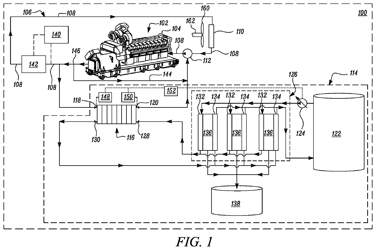
[0012]FIG. 1 illustrates a schematic view of an integrated thermal management and water purification system 100. The integrated thermal management and water purification system 100 may be retrofitted onto an existing heat source 102 such as, but not limited to, an engine for thermal management of the heat source 102 while also obtaining purified water using ambient air and heat from the heat source 102.

[0013]As shown in FIG. 1, the integrated thermal management and water purification system 100 includes a heat source 102. In the illustrated embodiment, the heat source 102 is embodied in the form of an engine 104. Although the engine 104 is illustrated herein, it may be noted that the engine 104 is non-limiting of this disclosure. Upon reviewing the present disclosure, it will be evident to persons skilled in the art that other types of heat s...


PUM


Abstract

A system for obtaining purified water includes a heat exchanger fluidly coupled to the heat source for receiving a thermal management fluid from the heat source, and a reservoir fluidly coupled with the heat exchanger to supply water, at an ambient temperature, for receiving heat from the thermal management fluid at the heat exchanger. A pump provides a pre-defined flow rate of the water from the reservoir to the heat exchanger based on a temperature gradient of the thermal management fluid across the heat exchanger. A purification device has a cold side chamber in fluid communication with the pump and the heat exchanger while a hot side chamber is in fluid communication with the heat exchanger and the reservoir. The cold and hot side chambers of the purification device thermally co-operate with each other to develop condensate therebetween from moisture present in the ambient air for forming water.

Description

TECHNICAL FIELD[0001]The present disclosure relates to a water purification system. More particularly, the present disclosure relates to an integrated thermal management and water purification system using a single pump for obtaining purified water.BACKGROUND[0002]Lately, conventional heat harnessing systems have been known to have increased complexity in design and structure. The increased complexity in design may arise, at least in part, due to an increased number and type of components that are typically required to effectively harness heat from a heat source, for example, a thermal management fluid of an engine. An example of such a conventional heat harnessing system, in this case—using a redundant circuit design for accomplishing various fluid flows and their concomitant heat transfers, may be found in the disclosure of Chinese patent 103397955.[0003]In addition to the above, several challenges may be encountered by the conventional heat harnessing systems as these challenges ...

Claims


Application Information

Patent Timeline
IPC IPC(8): C02F1/16C02F1/00B01D1/00
CPCC02F1/008C02F2209/40C02F2209/02C02F1/16B01D1/0082B01D1/0058
Inventor SAKARAY, UMAKANTHMURUGAN, DHANASEKARDANIELSON, CURTIS ALLEN
Owner CATERPILLAR INC
Why Eureka
Try Eureka