Switch cupboard with a cooling device which is subject to a rotation and cooling device for this

a technology of rotating cooling device and switch cupboard, which is applied in the direction of motors, engine fuctions, lighting and heating apparatus, etc., can solve the problems of destroying or disturbing the function of electrical and electronic components susceptible to moisture, and achieve the effect of high uptake capacity

Inactive Publication Date: 2008-05-13
PFANNENBERG GMBH
View PDF5 Cites 36 Cited by
  • Summary
  • Abstract
  • Description
  • Claims
  • Application Information

AI Technical Summary

Problems solved by technology

The switch cupboards participate in the rotation of the turbine spindle so that occuring condensation water is distributed and sprayed in the inner space of the switch cupboard with the result that the electrical and electronic components susceptible to moisture can be disturbed in their function or destroyed.

Method used


Image

  • Switch cupboard with a cooling device which is subject to a rotation and cooling device for this
  • Switch cupboard with a cooling device which is subject to a rotation and cooling device for this
  • Switch cupboard with a cooling device which is subject to a rotation and cooling device for this

Examples


Embodiment Construction

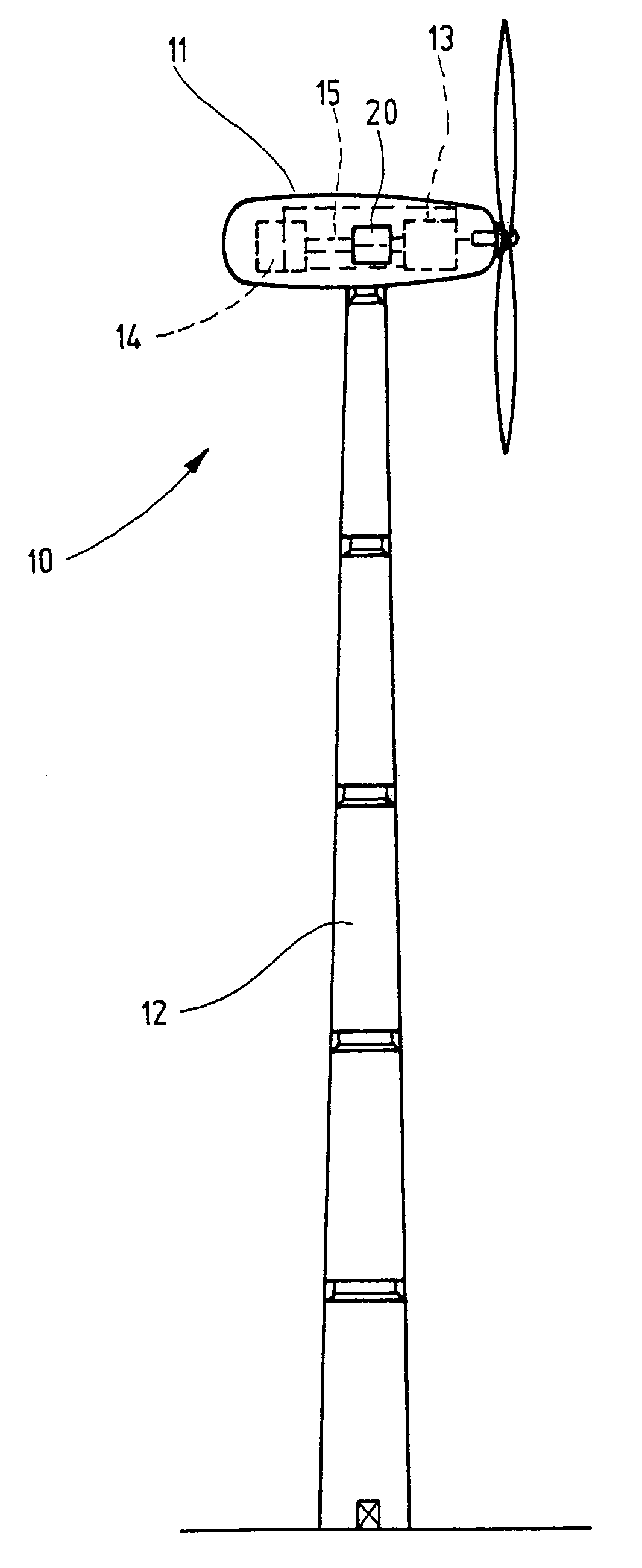
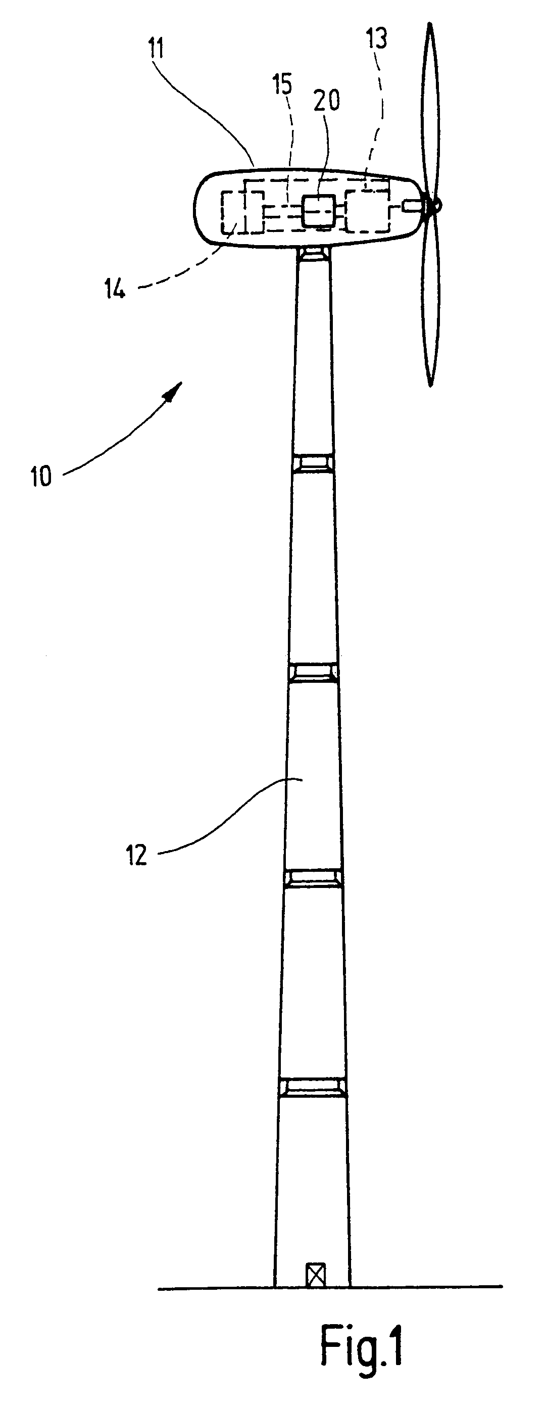
[0027]FIG. 1 shows a wind power station 10 configured in a known manner which comprises a columnar tower 12, a tower head 11, a wind driven turbine 13 and an electrical generator 14 placed in the tower head, whereby the turbine 13 set into rotation by wind transmits the movement of rotation over a rotor shaft 15 or a gear to the electrical generator which transforms the rotation energy into electrical current. A switch cupboard 20 configured in a known manner which rotates about its own axle in direction of the arrow x (FIGS. 2 and 3) is placed in the rotation housing 16 placed in the tower head 11. The switch cupboard 20 receives the electrical and electronical components and switching elements and consists of a housing 21 with a cooling device 30 placed in its inner space 23 which is made of a cold emitting device part 31 which is situated in the inner space 23 of the switch cupboard housing 21. Furthermore, the cooling device comprises a heat emitting device part 32 which is situ...


PUM

PropertyMeasurementUnit
areaaaaaaaaaaa
constant radiusaaaaaaaaaa
circular shapeaaaaaaaaaa

Abstract

The switch cupboard for receiving electrical and electronical components and switching elements which is subject to a rotation and which has at least one cooling device (30) with a cold emitting device part (31) placed in its inner space (23) and with a heat emitting device part (32) which is situated outside the switch cupboard (20) and which is placed for example in the tower head (11) of a wind power station is configured in such a manner that a condensate ring (41) is placed as a shell-shaped collecting trough (40) in the area of the cold side (31a) of the cooling device (30) which is placed in a wall (22) of the switch cupboard (20), cold side which is situated in the inner space (23) of the switch cupboard (20), whereby the inner space (42) is connected with a hose (50) guided out of the inner space (23) of the switch cupboard (20) which is configured as a spiral hose (50a) in the area of the warm side (32a) of the cooling device (30) situated outside the switch cupboard (20), whereby the spirally configured section (50a) of the hose (50) is configured as a spiral (51) with a constant radius or as an opening spiral (52) and whereby the axles of the rotor shaft (15) and of the condensate ring (41) enclosing the cooling body are parallel.

Description

FIELD OF APPLICATION[0001]This invention relates to a switch cupboard with a cooling device which is subject to a rotation and a cooling device for this according to the preambles of the claims 1 and 9.PRIOR ART[0002]One or several switch cupboards with electronic and electrical components and switching elements are placed in the tower heads of wind power stations, whereby these switch cupboards are equipped with cooling devices. The switch cupboards participate in the rotation of the turbine spindle so that occuring condensation water is distributed and sprayed in the inner space of the switch cupboard with the result that the electrical and electronic components susceptible to moisture can be disturbed in their function or destroyed.[0003]The aim of this invention is to avoid the above mentioned disadvantages.Aim, Solution, Advantage[0004]The invention provides a switch cupboard with the characteristics indicated in claim 1 to achieve this aim.[0005]Accordingly, the switch cupboar...

Claims


Application Information

Patent Timeline
Patent Type & Authority Patents(United States)
IPC IPC(8): F25B21/02
CPCB01D5/0042B01D5/009F03D11/00F05B2260/20F25D21/14Y02E10/722F03D80/60Y02E10/72Y02P70/10
Inventor PFANNENBERG, ANDREAS
Owner PFANNENBERG GMBH
Why Eureka
Try Eureka