Peltier cooler integrated with electronic device(s)

a technology of electronic devices and coolers, applied in the field of peltier coolers integrated with electronic devices, can solve the problems of preventing their use in new ways, and achieve the effect of effective cooling the small area and high outpu

Inactive Publication Date: 2004-08-12
SHISHOV ALEXANDER
View PDF5 Cites 41 Cited by
  • Summary
  • Abstract
  • Description
  • Claims
  • Application Information

AI Technical Summary

Benefits of technology

0007] A Peltier cooling systems is arranged with specially shaped thermocouples. These semiconductor elements appropriately doped to effect Peltier cooling / heating functions are also shaped to transmit heat away from a heat source in a radial direction to a peripheral region. In this way, a large area heat dump more effectively cools the small area of the heat generating device. Additionally, some versions also remove heat from a small area region in a cooling plane to separate plane displaced therefrom. Still further, some versions incorporate a special electronic arrangement whereby the cooling system and cooled system share a single electronic circuit. That is to say, the Peltier elements may be driven by the very same current as the cooled electronic device. A serial electronic circuit permits a single current to drive the electronic device and provide cooling effect.
0008] In a best version, an LED is placed between each thermocouple of a multiple couple system. Thus a light emitting diode array is formed to produce high output while the current is routed through a series of alternately doped Peltier elements to effect cooling. This configuration further benefits from a multiplying factor which is possible as a result of a radial arrangement which permits a Peltier `hot` side which is much larger in area than the Peltier `cold` side.

Problems solved by technology

While the systems and inventions of the art are designed to achieve particular goals and objectives, these concepts have limitations which prevent their use in new ways now possible.

Method used


Image

  • Peltier cooler integrated with electronic device(s)
  • Peltier cooler integrated with electronic device(s)
  • Peltier cooler integrated with electronic device(s)

Examples


Embodiment Construction

[0028] In accordance with each of preferred embodiments of the invention, a Peltier cooler integrated with electronic device or devices is provided. It will be appreciated that each of the embodiments described include both an apparatus and that the apparatus of one preferred embodiment may be different than the apparatus of another embodiment.

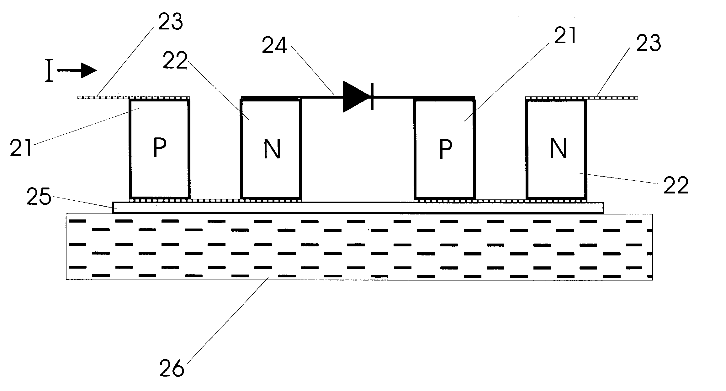
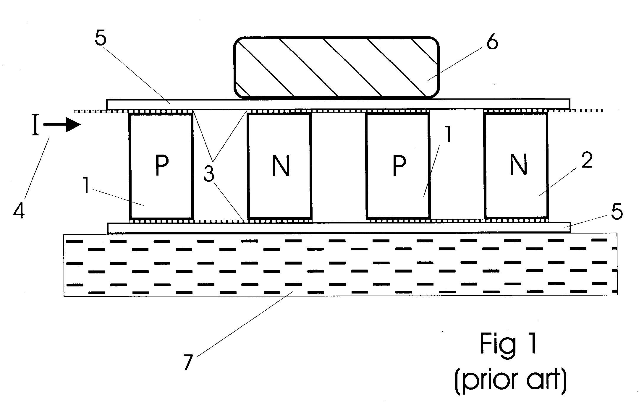
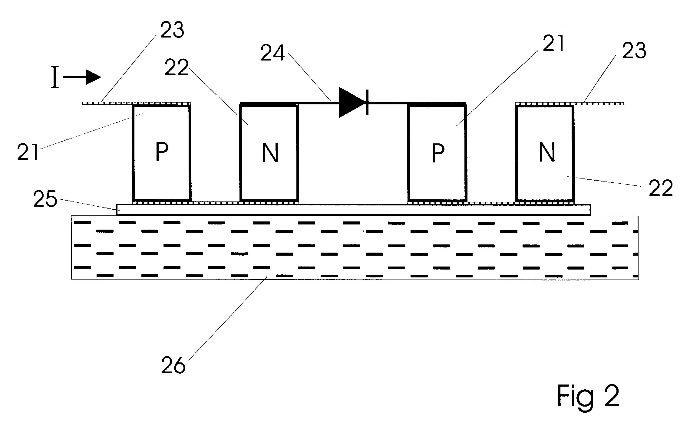
[0029] With reference to the drawing figures one will gain a more complete appreciation of these inventions. FIG. 1 illustrate a common Peltier cooler and in conjunction with a heat load. The device is primarily made of Peltier elements of `P`-type semiconductor material 1 and Peltier elements of `N`-type semiconductor material 2. These two semiconductor types are arranged in a spatially alternating fashion. The permits convenient electrical contact between elements. Each element has a `hot side` and a `cold side` in view of a predetermined current direction. For example, the current shown 4 in the Figure causes the top side for both `P` and `...


PUM


Abstract

A Peltier effect cooling device is formed in combination with an electronic device to form a unique thermal and electrical relationship. An electronic device to be cooled is placed in a serial electrical relationship between at least two thermoelectric couples while simultaneously being in thermal contact with a cold side of the cooler arrangement. The same current which produces the thermoelectric effect in the Peltier thermocouples also drives the electronic device. A balanced effect results as a higher driving current through the electronic device causes greater heating, it is offset by the added cooling due to a greater current in the thermocouples. In addition, a unique spatial arrangement provides improved heat distribution and transfer to a heat sink. Due to the unique shapes of Peltier elements, heat is pulled radially from a heat generating source and distributed at a peripheral region. Shaped Peltier elements are tapered from a small cold area to a large hot area to further magnify the transfer of heat.

Description

BACKGROUND OF THESE INVENTIONS[0001] 1. Field[0002] The field of these inventions includes semiconductor electronics and specifically semiconductors used to promote the Peltier effect for cooling of electronic components.[0003] 2. Prior Art[0004] Peltier coolers and the use of them to cool electronic elements and devices is well known. However, typical arrangements of these include a plurality of thermal couples in contact with two planar elements. Thus, there is a `hot` plane and a `cold` plane spatially removed therefrom. This system is invariably used in all Peltier configurations. In addition, the Peltier cooler and the device to be cooled are typically electrically isolated. That is, they are thermally coupled but are on different electronic circuits. The current passed through the Peltier cooler is not related to the current passed through the cooled device.[0005] While the systems and inventions of the art are designed to achieve particular goals and objectives, these concept...

Claims


Application Information

Patent Timeline
Patent Type & Authority Applications(United States)
IPC IPC(8): H01L23/38H01L27/15H01L33/64
CPCH01L23/38H01L27/15H01L33/645H01L35/32H01L2924/0002H01L2924/00H10N10/17
Inventor ABRAMOV, VLADIMIRAGAFONOV, DMITRYSCHERBAKOV, NIKOLAISHISHOV, ALEXANDERSUSHKOV, VALERYDRABKIN, IGORMARYCHEV, VLADIMIROSVENSKY, VLADIMIR
Owner SHISHOV ALEXANDER
Why Eureka
Try Eureka