Flavor source unit and flavor inhaler

a flavor source and flavor technology, applied in the field of flavor source units and flavor inhalers, can solve the problems of poor flavor addition to the air, air inhaled by the user does not uniformly contact the plurality of flavor pieces, etc., and achieve the effect of suppressing the excessive downsizing of the second cartridge 30, easy flavor addition, and suppressing the flow of air

Active Publication Date: 2020-03-19
JAPAN TOBACCO INC
View PDF0 Cites 2 Cited by
  • Summary
  • Abstract
  • Description
  • Claims
  • Application Information

AI Technical Summary

Benefits of technology

[0089]According to the embodiment, the columnar lump body 320 is disposed in such a way as to block the inside space of the cylindrical body side wall 313 by the lump body side face 323 contacting any portion of the inner surface of the cylindrical body side wall 313. The foregoing constitution suppresses the flow of the air passing through a gap formed between the lump body side face 323 and the inner surface of the cylindrical body side wall 313, and thus makes it easy to add the flavor to the air through the flavor pieces located inside the columnar lump body 320.
[0090]According to the embodiment, the first space 35 including the second space 36A is provided at least between the second cylindrical body end face 312 and the second lump body end face 322. The first space 35 may be provided between the first cylindrical body end face 311 and the first lump body end face 321. The foregoing constitution suppresses the excessive downsizing of the second cartridge 30 and thus improves the ease of production and handling of the second cartridge 30.
[0091]As described above, the second cartridge 30 according to the embodiment makes it possible to suppress the excessive downsizing of the second cartridge 30 and also improve the efficiency of the flavor addition to air.
[0092]According to the embodiment, the co

Problems solved by technology

On the other hand, if the filling rate of 95 percent or higher is failed to be achieved, there is a possibility that the air inhaled by the user does not uniformly contact the plurality of flavor pieces

Method used


Image

  • Flavor source unit and flavor inhaler
  • Flavor source unit and flavor inhaler
  • Flavor source unit and flavor inhaler

Examples


embodiment

[0052](Flavor Inhaler)

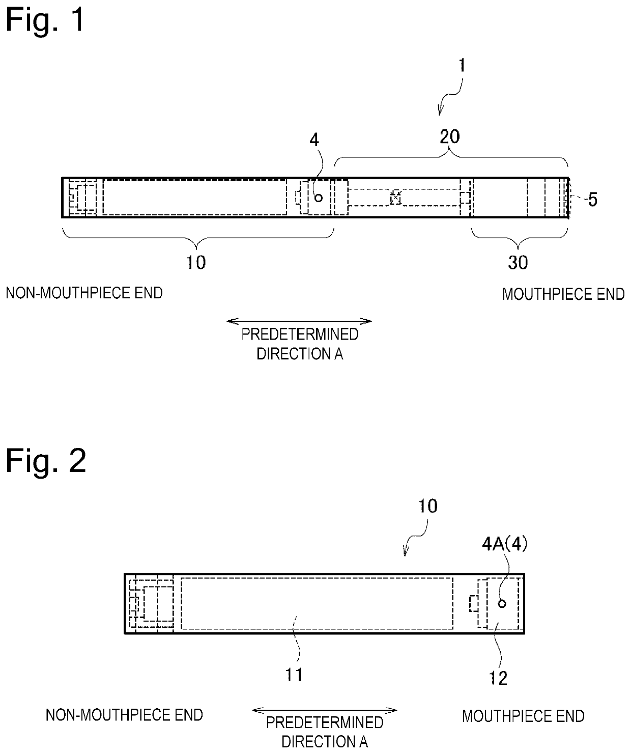
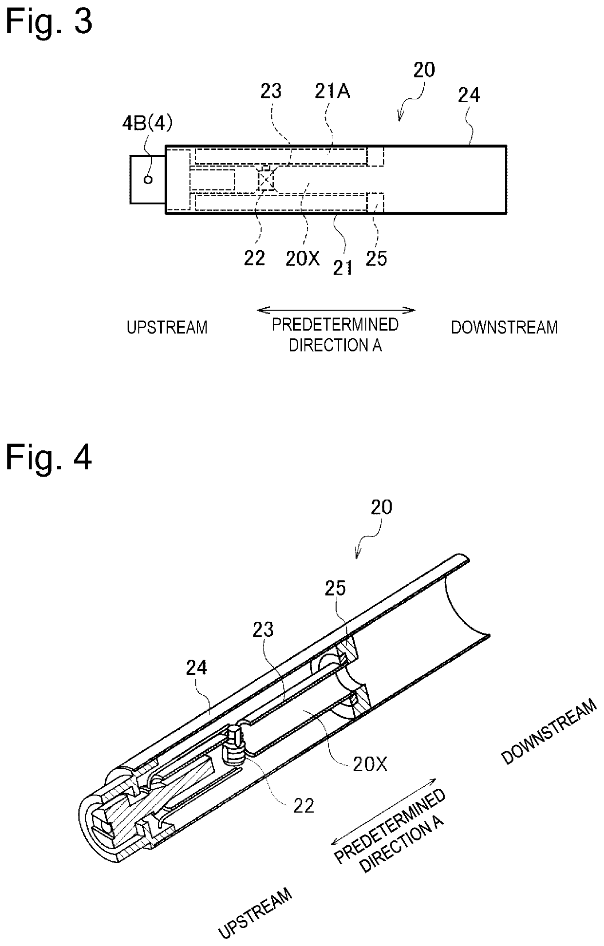
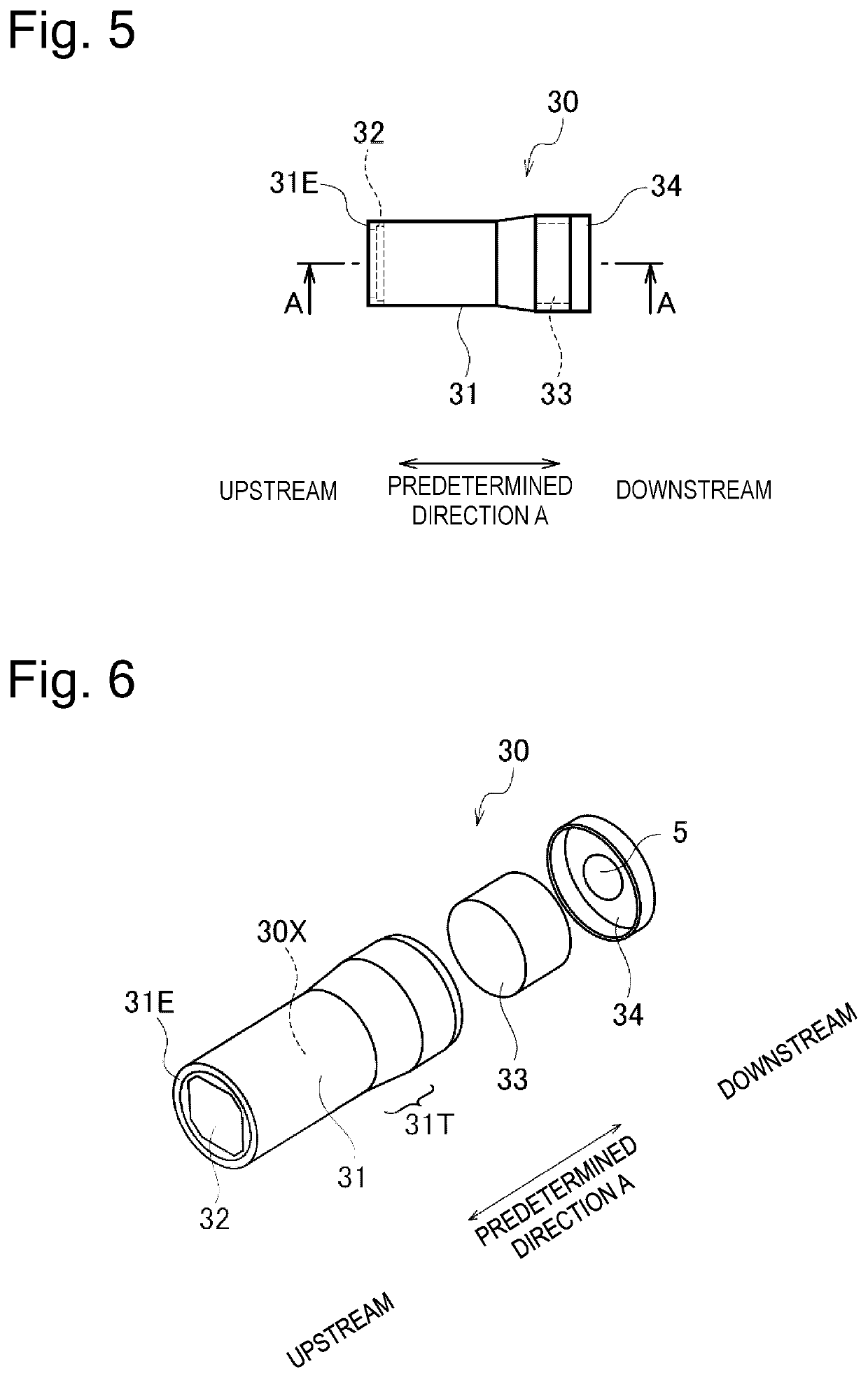
[0053]The following description explains a flavor inhaler according to an embodiment. FIG. 1 is a sectional view of a flavor inhaler 1 according to the embodiment. FIG. 2 is a sectional view of an electric power source unit 10 according to the embodiment. FIG. 3 is a sectional view of a first cartridge 20 according to the embodiment. FIG. 4 shows an internal structure of the first cartridge 20 according to the embodiment. It should be noted that a later-mentioned reservoir 21 is omitted in FIG. 4. FIG. 5 is a side view of a second cartridge 30 according to the embodiment. FIG. 6 is an exploded perspective view of the second cartridge 30 according to the embodiment. FIG. 7 is a sectional view of a cylindrical body 31 according to the embodiment (along line A-A of FIG. 5). FIG. 8 is a sectional view of the cylindrical body 31 according to the embodiment (along line B-B of FIG. 7). It should be noted that a columnar lump body (flavor source) is omitted in FIGS. 5 ...

modified example 1

[0097]A modified example 1 of the embodiment will be now described. The following description relates mainly to differences from the embodiment.

[0098]Specifically, according to the embodiment, the second space 36A is provided between the filter 33 (second end wall) and the second lump body end face 322, and the mesh body 32 (first end wall) is in contact with the first lump body end face 321.

[0099]According to the modified example 1, as illustrated in FIG. 11, the second space 36A is provided between the filter 33 and the second lump body end face 322, and a second space 36B is provided between the mesh body 32 and the first lump body end face 321. The second space 36B forms a portion of the first space 35B provided between the first cylindrical body end face 311 and the first lump body end face 321.

modified example 2

[0100]A modified example 2 of the embodiment will be now described. The following description relates mainly to differences from the embodiment.

[0101]Specifically, according to the embodiment, the second space 36A is provided between the filter 33 (second end wall) and the second lump body end face 322, and the mesh body 32 (first end wall) is in contact with the first lump body end face 321.

[0102]According to the modified example 2, as illustrated in FIG. 12, the second space 36 is not provided between the filter 33 and the second lump body end face 322, so that the filter 33 is in contact with the second lump body end face 322. On the other hand, the second space 36B is provided between the mesh body 32 and the first lump body end face 321. The second space 36B forms a portion of the first space 35B provided between the first cylindrical body end face 311 and the first lump body end face 321.

[0103]FIG. 12 describes the invention using the same constitution as in FIG. 9 for the sak...


PUM


Abstract

A flavor source unit includes a columnar lump body formed of a plurality of flavor pieces and a cylindrical body containing the columnar lump body. The cylindrical body includes a first cylindrical body end face that forms an air inflow end, a second cylindrical body end face that forms an air outflow end, and a cylindrical body side wall connecting an outer periphery of the first cylindrical body end face and an outer periphery of the second cylindrical body end face. The columnar lump body includes a first lump body end face that forms an air inflow end, a second lump body end face that forms an air outflow end, and a lump body side face that continues into an outer periphery of the first lump body end face and an outer periphery of the second lump body end face. The columnar lump body is disposed in such a way as to block an inside space of the cylindrical body side wall by the lump body side face contacting any portion of an inner surface of the cylindrical body side wall. A first space is provided at least either between the first cylindrical body end face and the first lump body end face or between the second cylindrical body end face and the second lump body end face.

Description

CROSS REFERENCE TO RELATED APPLICATIONS[0001]The present application is a continuation application of International Application No. PCT / JP2018 / 016948, filed on Apr. 26, 2018.TECHNICAL FIELD[0002]The invention relates to a flavor source unit and a flavor inhaler.BACKGROUND ART[0003]A flavor inhaler with a flavor source unit has been known. The flavor source unit includes a cylindrical body containing a plurality of flavor pieces, and a pair of end walls having air permeability. The end walls are each disposed in an end portion of the cylindrical body. For example, a space demarcated by the end walls and the cylindrical body is filled with the flavor pieces at a filling rate of 95 percent or higher.CITATION LISTPatent Literature[0004]PTL 1: International Patent Publication No. WO 2015-179388SUMMARY OF INVENTION[0005]A first characteristic is a flavor source unit comprising a columnar lump body that is formed of a plurality of flavor pieces, and a cylindrical body containing the column...

Claims


Application Information

Patent Timeline
IPC IPC(8): A24F40/20H05B1/02H05B3/46A24F40/42
CPCA24F40/46H05B3/46A24F40/20H05B1/0297A61M15/06A24F40/42A24D1/20A24F40/10A24B15/167A61M2205/8206
Inventor SHINKAWA, TAKESHIAKIYAMA, TAKESHI
Owner JAPAN TOBACCO INC
Why Eureka
Try Eureka