Suspension apparatus

a suspension apparatus and suspension technology, applied in the direction of shock absorbers, axle suspensions, liquid based dampers, etc., can solve the problems of air bubble entrapment, rapid drop of oil pressure, and gradual accumulation of air bubbles in working oil

Active Publication Date: 2015-04-09
HITACHI ASTEMO LTD
View PDF9 Cites 7 Cited by
  • Summary
  • Abstract
  • Description
  • Claims
  • Application Information

AI Technical Summary

Benefits of technology

[0016]With the configuration of [4], the piston retains the dividing member that divides the lower space into the upper positioning space which is a space positioned above the dividing member and the lower positioning space which is a space positioned below the dividing member, and the piston has the space communication hole that is a hole through which the upper positioning space communicates with the lower positioning space, and thus, even in a configuration where the suspension apparatus further includes the adjustment mechanism that adjusts the rate of a fluid passing through the space communication hole of the piston, and the operation portion for operation of the adjustment mechanism is arranged inside the upper portion space, it is possible to suppress occurrence of the impulse sound caused by occurrence of the air bubble entrapment in the space in which the operation portion is arranged.

Problems solved by technology

In the suspension apparatus according to JP-A-2009-85263, there is a problem in that air bubbles in working oil gradually gather around the plurality of adjusting bolts that are provided in each of the plurality of adjusting portions and air bubble entrapment is formed.
In addition, since the supply of the working oil into an oil chamber formed below the piston inside the working oil chamber is delayed, pressure in the oil chamber rapidly decreases, a gaseous component in the working oil is separated, and an air bubble grows.

Method used


Image

  • Suspension apparatus
  • Suspension apparatus
  • Suspension apparatus

Examples


Embodiment Construction

[0028]Hereinafter, embodiments of the invention will be described in detail with reference to the accompanying drawings.

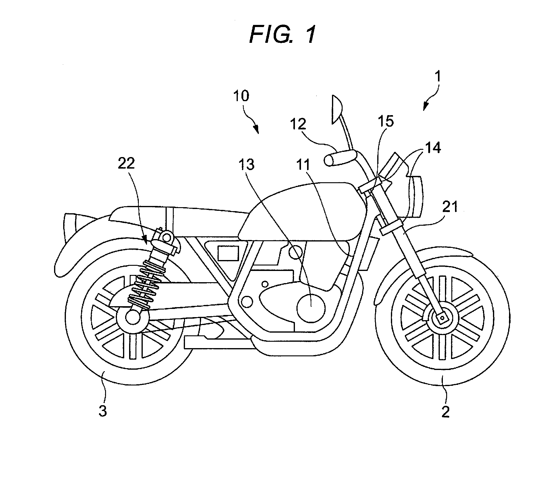
[0029]FIG. 1 is a view illustrating a schematic configuration of a motorcycle 1 according to the embodiment.

[0030]The motorcycle 1 includes a front wheel 2 that is a wheel on a front side; a rear wheel 3 that is a wheel on a rear side; and a main vehicle body 10 having a vehicle frame 11 that is a skeleton of the motorcycle 1, a handlebar 12, an engine 13 and the like. In addition, a front fork 21 is an example of a suspension apparatus that connects the front wheel 2 to the main vehicle body 10. The motorcycle 1 has a front fork 21 on each of the left and the right sides of the front wheel 2. The motorcycle 1 has a rear suspension 22 on each of the left and the right sides of the rear wheel 3, and the rear suspensions 22 connect the rear wheel 3 to the main vehicle body 10. FIG. 1 illustrates only the front fork 21 and the rear suspension 22 that are arranged on t...


PUM


Abstract

A suspension apparatus includes: a partition wall member that divides a space inside an inner tube into an upper space and a lower space; a cap that covers an upper opening portion of an outer tube; and a support member of which one end portion is retained by the cap, and of which the other end portion supports the other end portion of a piston rod, in which a through-hole is formed in a portion of the inner tube, an inner space of the piton rod is a space inside the piston rod and communicates with the lower space, the support member is a cylindrical member and forms an upper portion space, and the upper portion space communicates with the inner space of the piston rod, and at least one of the cap and the support member is provided with a communication path.

Description

CROSS-REFERENCE TO RELATED APPLICATIONS[0001]This application is based on and claims priority under 35 U.S.C. 119 from Japanese Patent Application No. 2013-209723 filed on Oct. 4, 2013, the entire content of which is incorporated herein by reference.BACKGROUND[0002]1. Technical Field[0003]The present invention relates to a suspension apparatus that is arranged between a vehicle body and a wheel in a two-wheeled vehicle or the like.[0004]2. Related Art[0005]In the related art, in a front fork in a two-wheeled vehicle known as an example of a suspension apparatus, bushes are fixed to an upper portion and a lower portion of an inner circumference of an outer tube, an inner tube is slidably fitted into the outer tube via the upper and the lower bushes, an annular oil chamber that is defined by the upper and the lower bushes is formed in a space between the inner circumference of the outer tube and an outer circumference of the inner tube, and thus a volume compensation chamber is formed...

Claims


Application Information

Patent Timeline
Patent Type & Authority Applications(United States)
IPC IPC(8): F16F9/34F16F9/18
CPCF16F9/185F16F9/341B62K25/08F16F9/43F16F9/22
Inventor YOSHIDA, KOJIRO
Owner HITACHI ASTEMO LTD
Why Eureka
Try Eureka