Robot system with end tool metrology position coordinates determination system

Active Publication Date: 2020-03-26
MITUTOYO CORP
View PDF0 Cites 3 Cited by
  • Summary
  • Abstract
  • Description
  • Claims
  • Application Information

AI Technical Summary

Benefits of technology

The patent describes a system for accurately positioning an end tool in a robot system. The system uses an XY scale and a first imaging configuration to capture images of a known XY scale at various positions in the robot's movement. These images are then processed to determine the position of the end tool with high accuracy. The system can be used in conjunction with a robot system to improve the accuracy of the end tool position.

Problems solved by technology

In various implementations, such systems may have a positioning accuracy of approximately 100 microns, as limited by certain factors (e.g., the rotary encoder performance in combination with the mechanical stability of the robot system, etc.).
While techniques such as those described in the '965 patent may be utilized for calibrating a robot system, in certain applications it may be less desirable to utilize such techniques (e.g., which may require significant time and / or may not provide a desired level of accuracy for all possible orientations of a robot during certain operations, etc.).

Method used


Image

  • Robot system with end tool metrology position coordinates determination system
  • Robot system with end tool metrology position coordinates determination system
  • Robot system with end tool metrology position coordinates determination system

Examples


Embodiment Construction

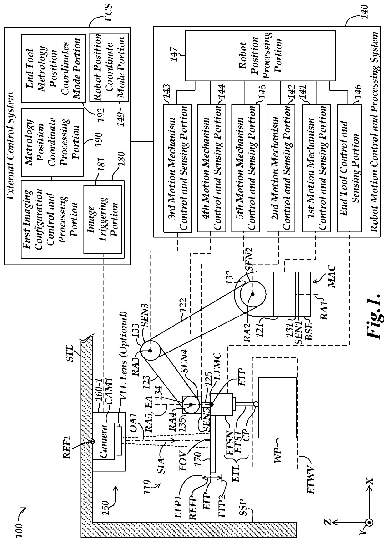
[0023]FIG. 1 is a block diagram of a first exemplary implementation of a robot system 100 including a robot 110 and an end tool metrology position coordinates determination system 150. The robot 110 (e.g., an articulated robot) includes a movable arm configuration MAC and a robot motion control and processing system 140. The end tool metrology position coordinates determination system 150 includes an end tool ETL, a first imaging configuration 160-1, an XY scale 170, an image triggering portion 181 and a metrology position coordinate processing portion 190. In the configuration of FIG. 1, the XY scale 170 is coupled to the end tool ETL. As will be described in more detail below, the first imaging configuration 160-1 has a first optical axis OA1 that may be parallel to a scale imaging axis direction SIA when in an operational configuration.

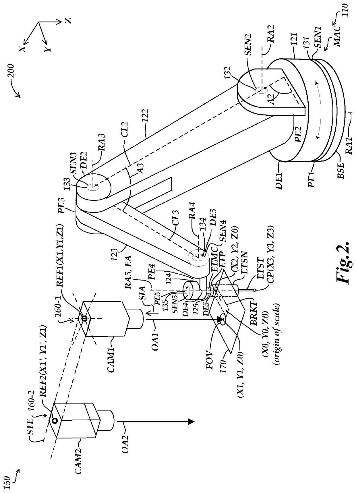
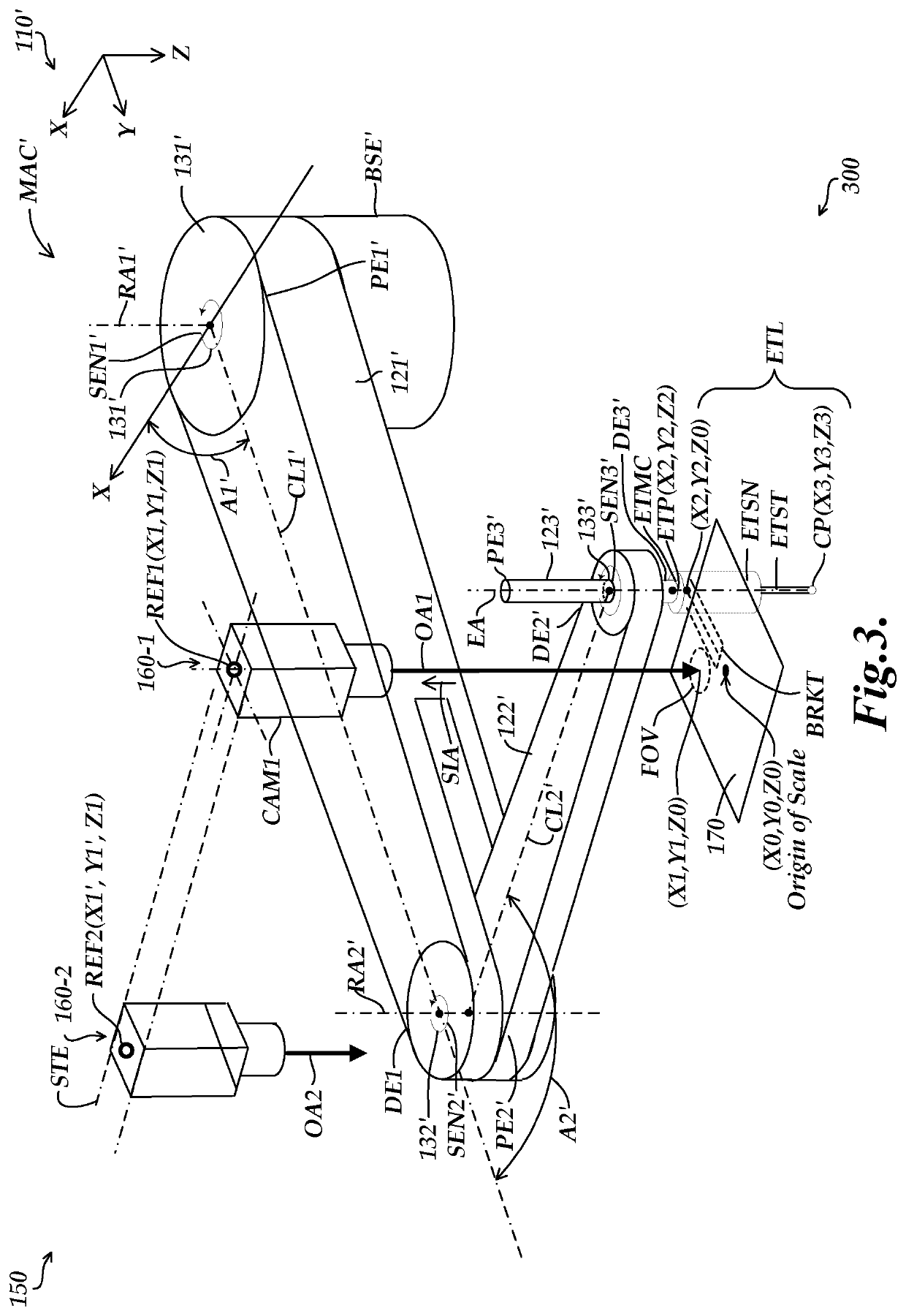
[0024]In the example of FIG. 1, the movable arm configuration MAC includes a lower base portion BSE, arm portions 121-125, motion mechanisms 131-1...


PUM


Abstract

An end tool metrology position coordinates determination system is provided for use with a robot. A first accuracy level defined as a robot accuracy (e.g., for controlling and sensing an end tool position of an end tool that is mounted proximate to a distal end of a movable arm configuration of the robot) is based on using position sensors (e.g., encoders) included in the robot. The system includes the end tool, an imaging configuration, XY scale, image triggering portion and processing portion. One of the XY scale or imaging configuration is coupled to the end tool and the other is coupled to a stationary element (e.g., a frame located above the robot). The imaging configuration acquires an image of the XY scale, which is utilized to determine a relative position that is indicative of the end tool position, with an accuracy level that is better than the robot accuracy.

Description

BACKGROUNDTechnical Field[0001]This disclosure relates to robot systems, and more particularly to systems for determining coordinates of an end tool position of a robot.Description of the Related Art[0002]Robotic systems are increasingly utilized for manufacturing and other processes. Various types of robots that may be utilized include articulated robots, selective compliance articulated robot arm (SCARA) robots, cartesian robots, cylindrical robots, spherical robots, etc. As one example of components that may be included in a robot, a SCARA robot system may typically have a base, with a first arm portion rotationally coupled to the base, and a second arm portion rotationally coupled to an end of the first arm portion. In various configurations, an end tool may be coupled to an end of the second arm portion (e.g., for performing certain work and / or inspection operations). Such systems may include position sensors (e.g., rotary encoders) utilized for determining / controlling the posi...

Claims


Application Information

Patent Timeline
IPC IPC(8): B25J9/16G05B19/402G05B19/401
CPCB25J9/1664G05B19/402B25J9/1697G05B19/401B25J9/161B25J9/1612B25J9/1692G05B2219/39011
Inventor NAHUM, MICHAELEMTMAN, CASEY EDWARD
Owner MITUTOYO CORP
Why Eureka
Try Eureka