Rotary disc type sensing element with multiple magnets and unevenly distributed magnetic fluxes

A technology with uniform distribution and sensing elements, which is applied in power metering, vehicle components, torque metering, etc., can solve problems such as distortion and difference of power-assist demand models, and inconsistency between power-assist output and power-assist demand, and achieve low cost and simple structure Effect

Inactive Publication Date: 2013-11-06
湖南双创部落信息咨询服务有限责任公司
View PDF7 Cites 2 Cited by
  • Summary
  • Abstract
  • Description
  • Claims
  • Application Information

AI Technical Summary

Problems solved by technology

[0016] Disadvantages (1) Using two permanent magnets with no difference to represent the fixed positions of the two pedals, only multiple Halls can be used to represent the rotational positions of the pedals: the two permanent magnets have no difference, and the advantages It is possible to indicate the fixed position of the two pedals regardless of the left and right feet, so that the left and right feet can generate power assistance requirements, which can produce the same motor power assistance effect; but the disadvantage is that the permanent magnet itself cannot indicate the rotation position of the pedals, but only Multiple Halls can be set at different corner positions to indicate the rotational position of the pedal, so one Hall cannot be used, but multiple Halls must be used
[0017] Disadvantage (2) You can’t use only one Hall, but three Halls will inevitably cause the original segmentation error of the three control signals, which will distort the power-assisted demand model, and naturally produce power-assisted output inconsistent with the power-assisted demand: whether the power-assisted bicycle is one or two For a motor, the sensing signal for controlling the motor can only be achieved by inputting a sensing signal into the motor controller to achieve the purpose of controlling the motor; while the patent uses three Halls to control the motor, it is necessary to use the three Halls of the three Halls to control the motor. The signals are combined into one combined control signal before being input to the motor controller
The sensing parameters of the three Halls cannot be the same, especially due to changes in ambient temperature and long-term use, the sensing parameters of the three Halls may vary greatly. The output voltages are different, resulting in different power output of the motor, and the power output is inconsistent with the power demand; similarly, when the power demand is the same, the outputs of different Halls may be the same voltage, resulting in the same power output of the motor, and also There is a problem that the power output is inconsistent with the power demand
However, such a structure limits the adjustable depth of the permanent magnet block on the rotating disk, resulting in only one sensing model for one sensor

Method used


Image

  • Rotary disc type sensing element with multiple magnets and unevenly distributed magnetic fluxes
  • Rotary disc type sensing element with multiple magnets and unevenly distributed magnetic fluxes
  • Rotary disc type sensing element with multiple magnets and unevenly distributed magnetic fluxes

Examples


Embodiment 1

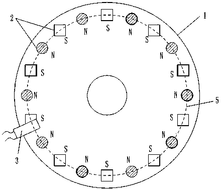
[0062] Embodiment 1. Rotary disk sensor element with non-uniform distribution of magnetic flux by multiple magnetic blocks

[0063] Such as figure 1 , 3 , 4, 5, 20 permanent magnet blocks 2 are fixedly arranged on the rotating disk 1 with a diameter of 10.0 cm by injection molding of a high-strength plastic.

[0064] All permanent magnet blocks 2 are evenly distributed in a circular trajectory, and each permanent magnet block 2 is fixed on a circular trajectory line 5 with a diameter of 9.0 cm, that is, the distance from each permanent magnet block 2 to the center of the circle where the circular trajectory line 5 is located is the same , The distance between adjacent permanent magnet blocks 2 is the same. The magnetic flux of the permanent magnet block 2 is 146---279 (B·H)max / KJ·m -3 Different selection values ​​within the range, and the magnetic flux of adjacent permanent magnet block 2 is not equal. There are two permanent magnet blocks 2 and the holes on the rotating ...

Embodiment 2

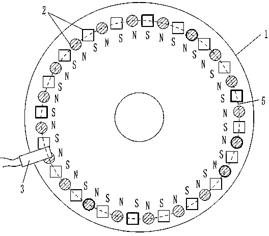
[0075] Embodiment 2. Rotary disk sensor element with uneven distribution of magnetic flux with high-density multi-magnetic blocks

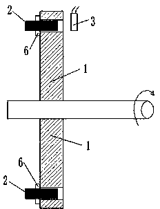
[0076] Such as figure 2 , 3 , 4, 5, one surface of a high-strength aluminum rotating disk 1 with a diameter of 10.0 cm is provided with 40 permanent magnet blocks 2 with a diameter of 0.4-0.6 cm. The magnetic flux of the permanent magnet block 2 is 146---279 (B·H)max / KJ·m -3 Different selection values ​​within the range, and the magnetic flux of the adjacent permanent magnet block 2 is not equal, Hall 3 keeps a distance of 0.2 cm from each permanent magnet block 2 in the rotating state, so that each permanent magnet block 2 that is rotating Hall 3, Hall 3 can generate a corresponding rectangular wave electrical signal output. The structures of other rotating disk 1, permanent magnet block 2, and Hall 3 are the same as those in embodiment 1.


PUM

PropertyMeasurementUnit
diameteraaaaaaaaaa
diameteraaaaaaaaaa
diameteraaaaaaaaaa

Abstract

The invention discloses a turntable sensing element with unevenly distributed magnetic fluxes of magnetic blocks, belongs to the technical field of providing signals by magnetic induction, and particularly relates to a technology for carrying out multi-point magnetic induction to provide control signals on a rotating component. A plurality of permanent magnet blocks which are distributed in a ring are fixedly arranged on a rotating plate; the magnetic fluxes of at least two permanent magnet blocks are different; the magnetic polarities of the adjacent permanent magnet blocks are opposite at one side of the rotating plate, namely the magnetic polarity distribution mode of all permanent magnet blocks at one side of the rotating plate is an N pole, an S pole, the N pole ...; and halls on the fixing plate are arranged at the positions near the permanent magnet blocks. The turntable sensing element has the advantages that the halls can obtain rectangular wave signals by an opposite distribution mode of the magnetic polarities NS of the adjacent permanent magnet blocks; the signals can be conveniently subjected to digital treatment, the rectangular wave signals can present the positions of the permanent magnet blocks on the rotating plate by difference of the magnetic fluxes, and uses of different rectangular waves are determined.

Description

[0001] technical field [0002] The invention belongs to the technical field of providing signals by magnetic induction, and in particular relates to the technology of providing control signals by multi-point magnetic induction on a rotating component. Background technique [0003] The Chinese patent 201020295192.0 "Claw Type Torque Sensing Device" applied by Yebao Vehicle Material Industry (Kunshan) Co., Ltd. discloses a sensing device for power-assisted bicycles. The sensing device includes a magnetic part and an elastic part to sense the torque. sensing device. After a long time of use, the change of the elastic coefficient of the elastic member will lead to changes in the sensing signal and the control effect of the controlled motor, and the power-assisted effect will not match the power-assisted needs of people. Moreover, the design structure of the elastic member is complex and the manufacturing cost is high. [0004] The Chinese patent 01201843.0 "Automatic Detectio...

Claims


Application Information

Patent Timeline
Patent Type & Authority Applications(China)
IPC IPC(8): B62M6/50G01L3/00G01P3/481
Inventor 黄强
Owner 湖南双创部落信息咨询服务有限责任公司
Why Eureka
Try Eureka