Method for detecting object border of 3D printer

a 3d printer and object technology, applied in the field of 3d printers, can solve the problems of 3d printers of related art may misjudge about the 3d object and potential mistakes, and achieve the effect of quick and accurate detection of the position

Active Publication Date: 2020-03-26
XYZPRINTING +1
View PDF0 Cites 2 Cited by
  • Summary
  • Abstract
  • Description
  • Claims
  • Application Information

AI Technical Summary

Benefits of technology

[0009]The disclosure is directed to a method for detecting object border of 3D printer, which may quickly and accurately detect the position of a 3D object upon a printing platform of a 3D printer.
[0011]In comparison with related art, even if a printing platform of a 3D printer is not in a rectangular shape, the 3D printer may still quickly and accurately detect whether a 3D object to be printed is fully located within an effective range of the printing platform, which is very useful and convenient.

Problems solved by technology

However, if the printing platform 1 is not in a rectangular shape, using the aforementioned approach to detect the position of the 3D object 2 upon the printing platform 1 may cause some potential mistakes.
In conclusion, the 3D printer of related art may misjudge about the 3D object 2 due to the inappropriate bounding box 21.

Method used


Image

  • Method for detecting object border of 3D printer
  • Method for detecting object border of 3D printer
  • Method for detecting object border of 3D printer

Examples


first embodiment

[0041]FIG. 5 is a schematic diagram showing an object border of the present invention. In the embodiment as shown in FIG. 5, the printing platform 42 is in a round shape.

[0042]As shown in FIG. 5, after the processor 41 projects a 3D object onto a 2D plane, a plurality of 2D coordinates can be obtained. The processor 41 may perform a calculation to these 2D coordinates for generating a 2D convex hull 60, wherein the 2D convex hull 60 is defined for indicating the border of the 3D object. Also, the processor 41 obtains all vertexes 601 of the 2D convex hull 60. In particular, these vertexes 601 are all obtained from the plurality of 2D coordinates of the 3D object. In a first embodiment, the processor 41 is to calculate a distance between each vertex 601 of the 2D convex hull 60 and a circle center 421 of the printing platform 42 respectively, and compares each distance with a radius of the printing platform 42 respectively, so as to determine whether the 3D object as a whole is withi...

second embodiment

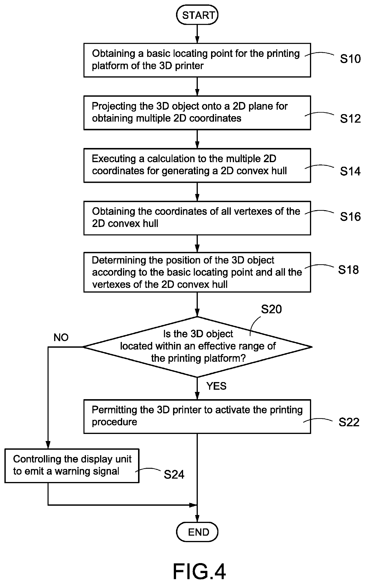
[0048]After the step S32, the processor 41 calculates a distance between each of the vertexes 601 of the 2D convex hull 60 and the circle center 421 of the printing platform 42 respectively (step S34), and determines if any of the calculated distances is longer than the radius of the printing platform 42 (step S36). In this embodiment, the processor 41 will determine that the 3D object as a whole is not fully located within the effective range of the printing platform 42 if any one of the calculated distances is longer that the radius of the printing platform 42 (step S38). On the other hand, the processor 41 will determine that the 3D object as a whole is fully located within the effective range of the printing platform 42 if all of the calculated distances are equal to or shorter than the radius of the printing platform 42 (step S40). After the step S38 or the step S40, the processor 41 may further perform the step S20 in FIG. 4, so as to determine whether the 3D printer 4 is perm...

third embodiment

[0055]Please refers to FIG. 8 at the same time. FIG. 8 is a schematic diagram showing an object border of the present invention. In one embodiment, the processor 41 may generate multiple straight lines that are respectively passing through one of the vertexes 601 and the basic locating point 420, obtain respectively a maximum distance Lmax between the basic locating point 420 and an intersection point of the circle equation and each straight line, and determines whether each distance between each of the vertexes 601 and the basic locating point 420 is equal to or shorter than the corresponding maximum distance Lmax (step S58). As discussed above, the step S58 is only used to determine whether the vertexes 601 of the 2D convex hull 60 are belonging to the aforementioned exception, so in some scenarios the step S58 in FIG. 9 is not necessary to be executed.

[0056]If the determination at the step S56 is positive (if the step S58 exists, the determination at the step S58 should be also p...


PUM

PropertyMeasurementUnit
distancesaaaaaaaaaa
radiusaaaaaaaaaa
sizeaaaaaaaaaa

Abstract

A method for detecting object border of 3D printer (4) includes following steps: obtaining a basic locating point (420) of a printing platform (42) of the 3D printer (4); projecting an imported 3D object onto a 2D plane of the 3D printer (4) for obtaining a plurality of 2D coordinates of the 3D object; calculating a 2D convex hull (60) according to the plurality of 2D coordinates; obtaining all vertexes (601) of the 2D convex hull (60); determining the position of the 3D object based on the basic locating point (420) in company with all the vertexes (601) of the 2D convex hull (60); and, permitting the 3D printer (4) to activate a printing procedure only if the 3D object is determined fully locating inside an effective range of the printing platform (42).

Description

BACKGROUND OF THE INVENTION1. Technical Field[0001]The technical field relates to a 3D printer, and specifically relates to a method for detecting a border of an object for a 3D printer.2. Description of Related Art[0002]A 3D printer is operated to control its printing nozzle to spray liquid material onto corresponding positions upon its printing platform based on an imported 3D object, so as to print a physical 3D model having an identical shape and appearance as the imported 3D object. Before the printing procedure is activated, a detecting procedure has to be previously performed by the 3D printer for detecting an arranged position of the 3D object imported by the user, so as to find out the border of the 3D object and ensure that the 3D object is in an effective range of the printing platform and prevent the printing procedure from failing.[0003]Generally, a virtual bounding box will be created and used by a 3D printer of related art for roughly determining the arranged position...

Claims


Application Information

Patent Timeline
Patent Type & Authority Applications(United States)
IPC IPC(8): B29C64/393B33Y50/02G05B19/4099
CPCG05B19/4099B29C64/393G05B2219/49023B33Y50/02B33Y30/00B29C64/118B29C64/20B29C64/209B29C64/245B29C64/264B29C64/30B33Y10/00B33Y40/00B29C64/386G05B2219/35134G05B2219/49007G06F30/00G06F2111/20G06F2203/04103G06T15/10G06T19/20G06T2219/2021
Inventor CHU, CHUNG-KANG
Owner XYZPRINTING
Why Eureka
Try Eureka