Unlock instant, AI-driven research and patent intelligence for your innovation.

Liquid ejecting device and liquid ejecting method

Active Publication Date: 2020-04-02
MIMAKI ENG
View PDF0 Cites 1 Cited by
  • Summary
  • Abstract
  • Description
  • Claims
  • Application Information

AI Technical Summary

Benefits of technology

The present invention provides a method for reducing the influence of abnormal nozzles in a liquid ejection system. By adjusting the ejection position and amount of liquid to be ejected by other nozzles, the influence of the abnormal nozzle is reduced. Additionally, information associating the influence degree of each ejection position is used to select the ejection position with the greatest influence and increase the amount of liquid ejected by other nozzles to reduce the influence of the abnormal nozzle. Overall, this method improves the efficiency and accuracy of liquid ejection systems.

Problems solved by technology

However, in this case, it is sometimes difficult to sufficiently suppress the influence of the presence of the abnormal nozzle only by simply considering the amount of misalignment of the amount of ink and the like.
However, in this case, since the amount of ink to an ejection position different from the original ejection position of the abnormal nozzle is adjusted, the influence of the abnormal nozzle may not be sufficiently reduced even if the total amount of ink is simply combined.

Method used


Image

  • Liquid ejecting device and liquid ejecting method
  • Liquid ejecting device and liquid ejecting method
  • Liquid ejecting device and liquid ejecting method

Examples


Embodiment Construction

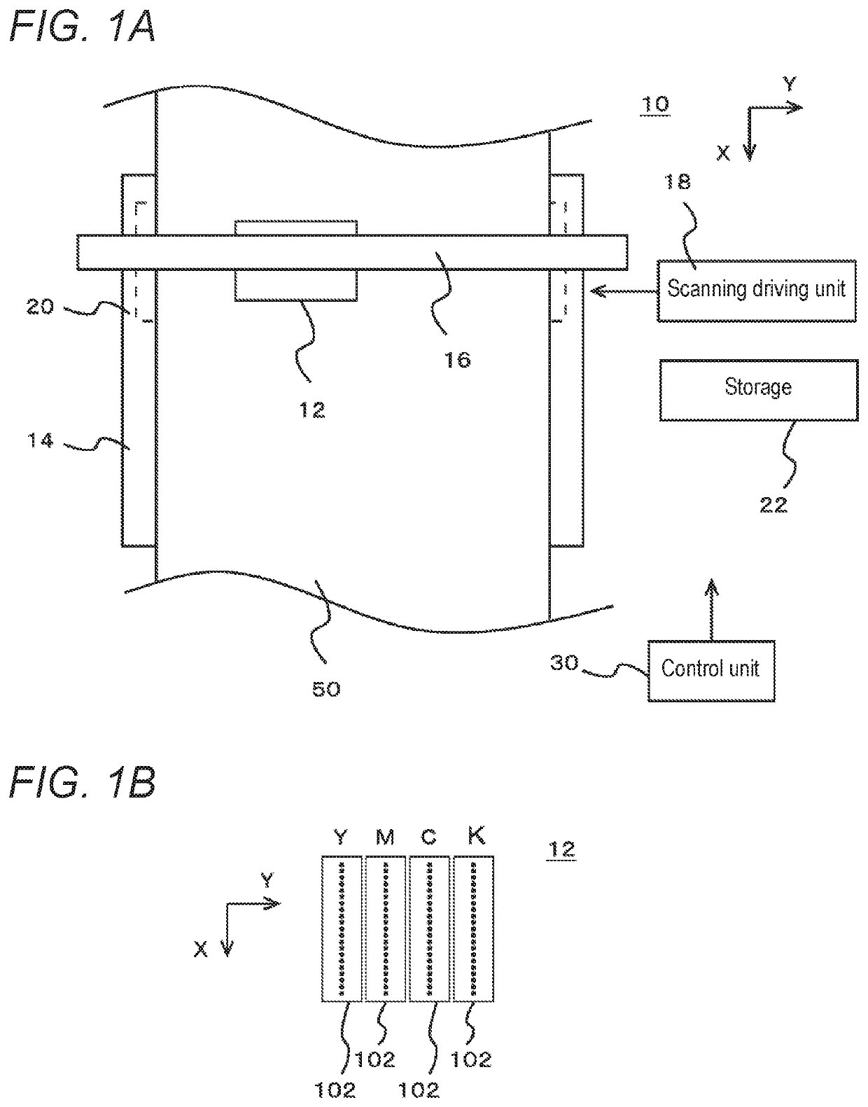
[0036]Hereinafter, an embodiment according to the present disclosure will be described with reference to the drawings. FIGS. 1A and 1B are views describing a printing apparatus 10 according to one embodiment of the present disclosure. FIG. 1A shows one example of a configuration of a main part of the printing apparatus 10. FIG. 1B shows one example of a configuration of a head unit 12 in the printing apparatus 10. Note that, except for the points described below, the printing apparatus 10 may have features same as or similar to the known inkjet printers. For example, the printing apparatus 10 may further have a configuration same as or similar to a known inkjet printer, in addition to the configuration described below.

[0037]The printing apparatus 10 is an example of a liquid ejecting device that ejects liquid through an inkjet method, and performs printing through the inkjet method on a medium (media) 50 to be printed. In this case, the medium 50 is an example of an ink ejecting tar...


PUM


Abstract

An liquid ejecting device includes an inkjet head, a scanning driving unit, a storage, an influence degree storage that stores influence degree information, and a control unit. The influence degree information indicates a magnitude of an influence generated at one ejection position by forming dots of the liquid at each of a plurality of ejection positions. The control unit causes other nozzles to eject a larger amount of liquid than at a normal time with respect to at least a part of the ejection position where the liquid is ejected by the other nozzles in the vicinity of an abnormal nozzle at the time of main scan, and selects an ejection position to which the other nozzle ejects a larger amount of the liquid than the normal time based on the influence degree information.

Description

CROSS REFERENCE TO RELATED APPLICATIONS[0001]This application claims the priority benefit of Japanese Patent Application No. 2018-187444, filed on Oct. 2, 2018. The entirety of the above-mentioned patent application is hereby incorporated by reference herein and made a part of this specification.TECHNICAL FIELD[0002]The present disclosure relates to a liquid ejecting device and a liquid ejecting method.DESCRIPTION OF THE BACKGROUND ART[0003]Various methods have been conventionally proposed for an inkjet recording apparatus to suppress degradation of image quality caused by ejection failure of an ink from a nozzle. For example, Japanese Unexamined Patent Publication No. 2017-13284 discloses a method of complementary control in which complementary ejection is performed by a nearby nozzle so as to compensate for the amount of ink not ejected by an abnormal nozzle (defective nozzle).SUMMARY[0004]In the complementary control disclosed in the configuration of Japanese Unexamined Patent Pu...

Claims


Application Information

Patent Timeline
IPC IPC(8): B41J2/045
CPCB41J2/04586B41J2/0451B41J2/01B41J2/2103B41J2/2139B41J2/2121B41J2/2128H04N1/4057H04N1/4015
Inventor FURUYA, CHIKAHIOKI, WATARU
Owner MIMAKI ENG
Features
  • R&D
  • Intellectual Property
  • Life Sciences
  • Materials
  • Tech Scout
  • Unparalleled Data Quality
  • Higher Quality Content
  • 60% Fewer Hallucinations
Learn More