

Mechanical perforator with guide skates
a technology of mechanical perforators and guide skates, which is applied in the direction of drilling casings, drilling pipes, borehole/well accessories, etc., can solve the problems of limiting the duty cycle of mechanical perforators, unable to achieve widespread commercial use, and unable to achieve the effect of widespread commercial us
- Summary
- Abstract
- Description
- Claims
- Application Information
AI Technical Summary
Benefits of technology
Problems solved by technology
Method used
Image

Examples
Embodiment Construction
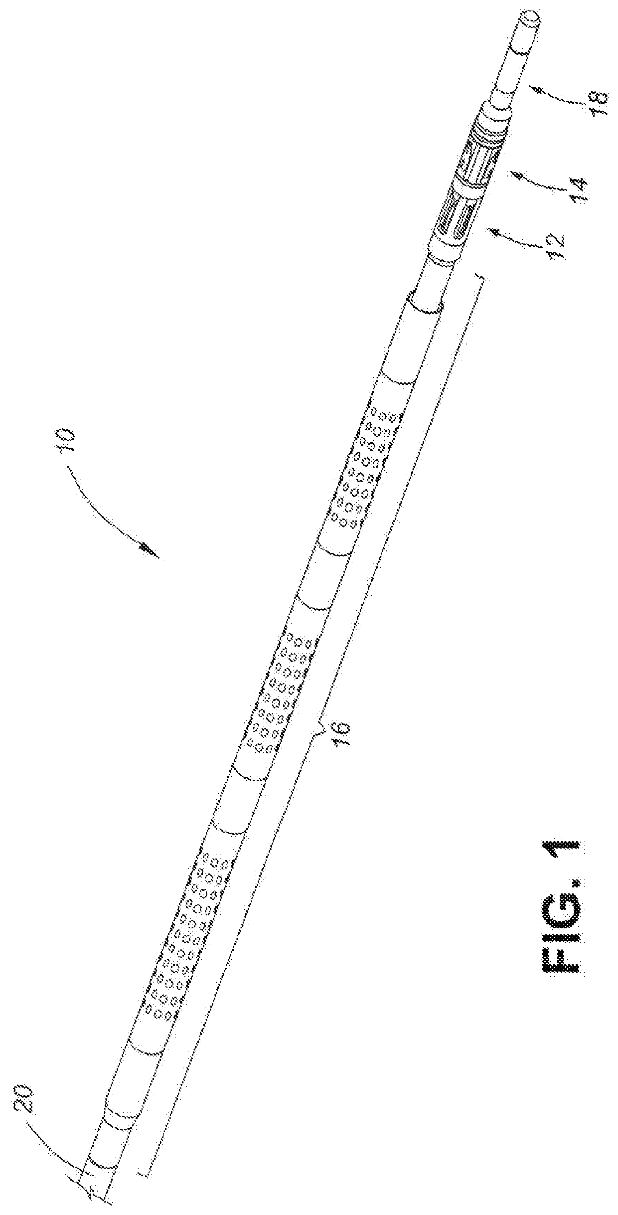
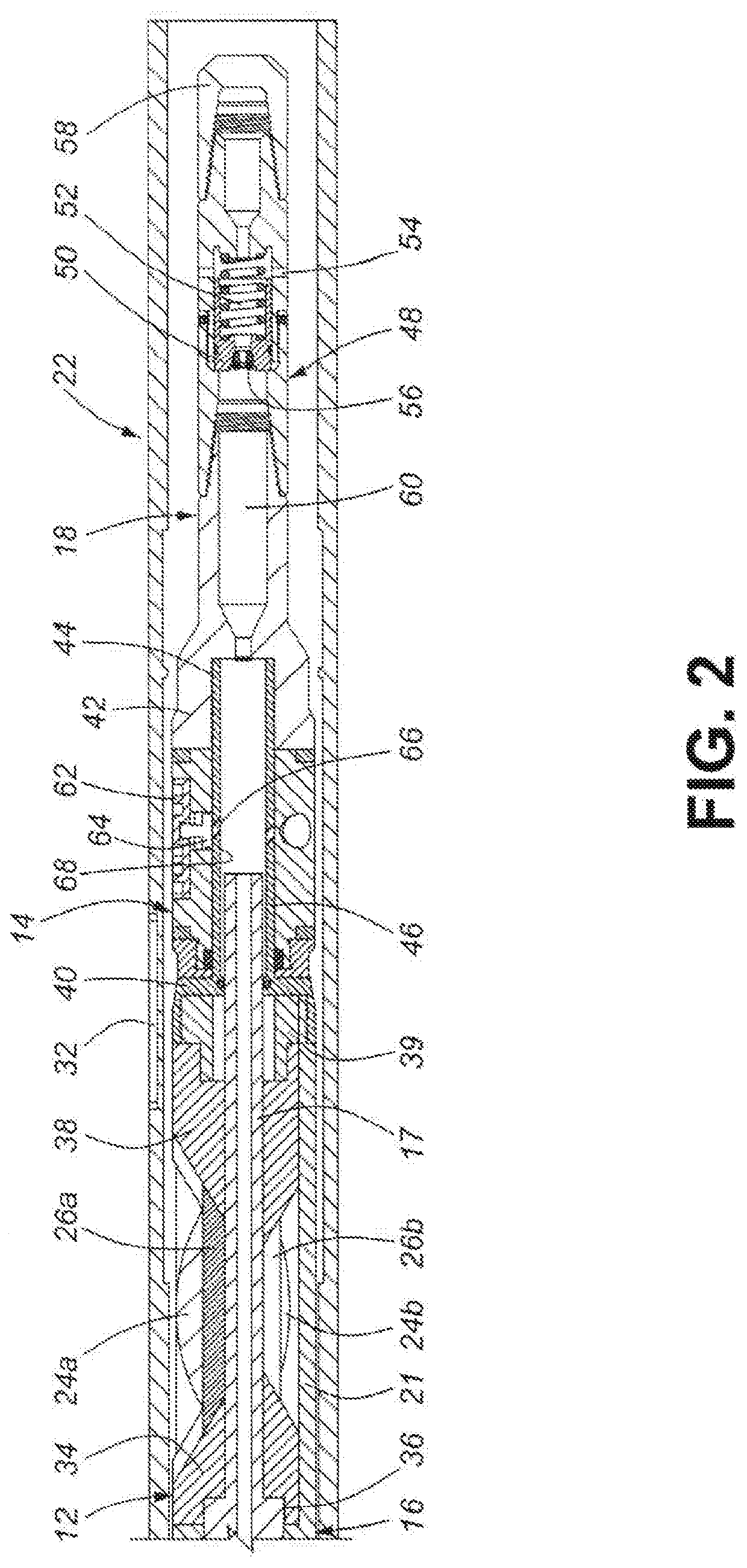
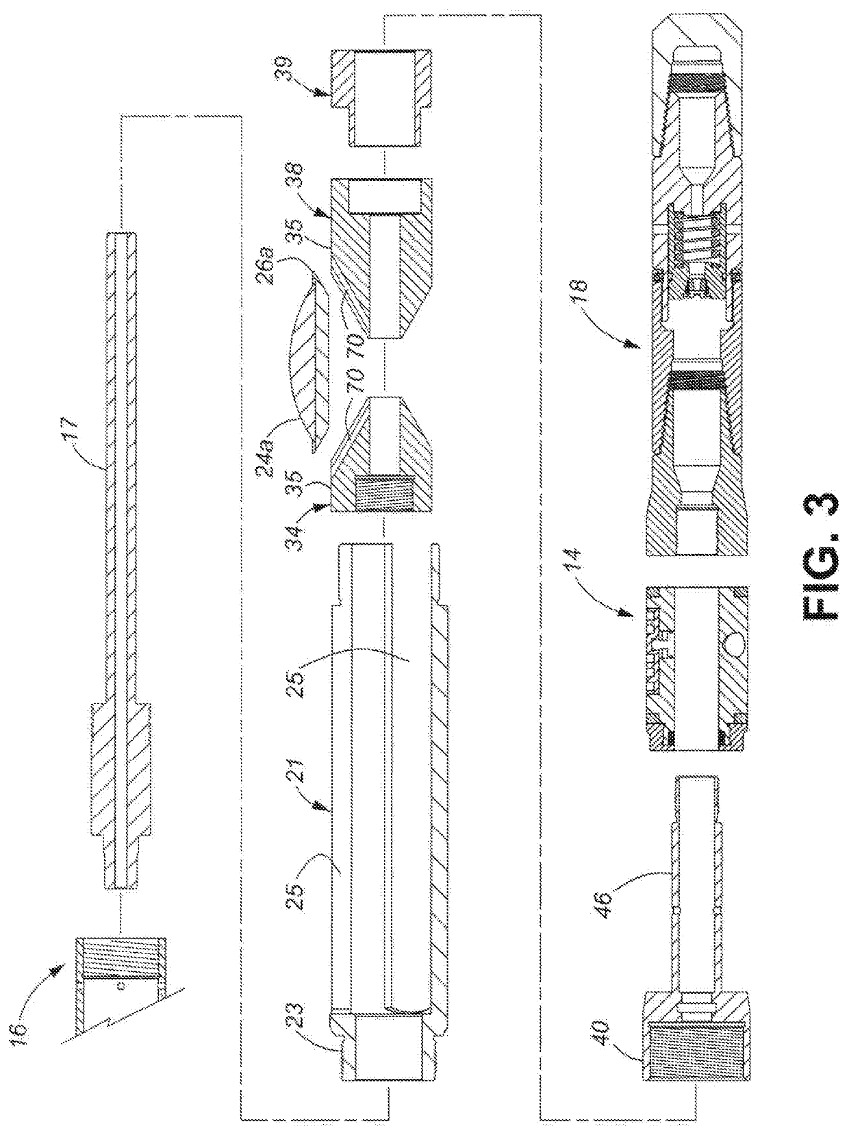
[0034]The invention provides a mechanical perforator with at least one perforator blade and at least one guide skate for use with mechanically perforated well casing collars in a casing string used to line a hydrocarbon well bore. The at least one guide skate guides the at least one perforator blade of the mechanical perforator into alignment with at least one machined-away area of a mechanically perforated well casing collar. The machined-away area(s) Is designed to facilitate mechanical perforation of the casing collar by the perforator blade(s). The guide skate(s) is normally urged to a retracted condition by springs, or the like. Fluid pressure pumped into the mechanical perforator moves the guide skate(s) to a deployed condition in which it is guided by a guide and lock structure within the mechanically perforated well casing collar to a lock recess in the well casing collar that retains the guide skate to lock the mechanical perforator in position for perforating the well casi...
PUM
 Abstract
Description
Claims
Application Information