Surgical Suction Filter

Active Publication Date: 2020-04-09
SUSTAIN MEDICAL LLC
View PDF0 Cites 3 Cited by
  • Summary
  • Abstract
  • Description
  • Claims
  • Application Information

AI Technical Summary

Benefits of technology

The patent describes a filter assembly for removing fluid and debris from a surgery. The assembly includes a filter element with a unique design to prevent clogging. The filter element has a conical body with a mouth, closed bottom, and a tapering wall with small orifices. A container is provided for holding the filter element, and a cap is also provided for covering the mouth. The cap has its own conical wall with a threaded interface for attaching a suction tool. The technical effect is that the filter assembly provides an efficient and effective way to remove fluid and debris from surgery, reducing the risk of complications and improving patient safety.

Problems solved by technology

One problem with in-line filters of this type is that they are prone to blockage from surgical debris, such as large bone pieces.
In that event, the filter element must be manually unblocked during the surgery, which inherently has a detrimental effect on the surgical procedure.
Moreover, when the filter element is returned to its operative configuration the integrity of the suction path can be compromised, requiring further attention to the filter element.

Method used


Image

  • Surgical Suction Filter
  • Surgical Suction Filter
  • Surgical Suction Filter

Examples


Embodiment Construction

[0034]For the purposes of promoting an understanding of the principles of the disclosure, reference will now be made to the embodiments illustrated in the drawings and described in the following written specification. It is understood that no limitation to the scope of the disclosure is thereby intended. It is further understood that the present disclosure includes any alterations and modifications to the illustrated embodiments and includes further applications of the principles disclosed herein as would normally occur to one skilled in the art to which this disclosure pertains.

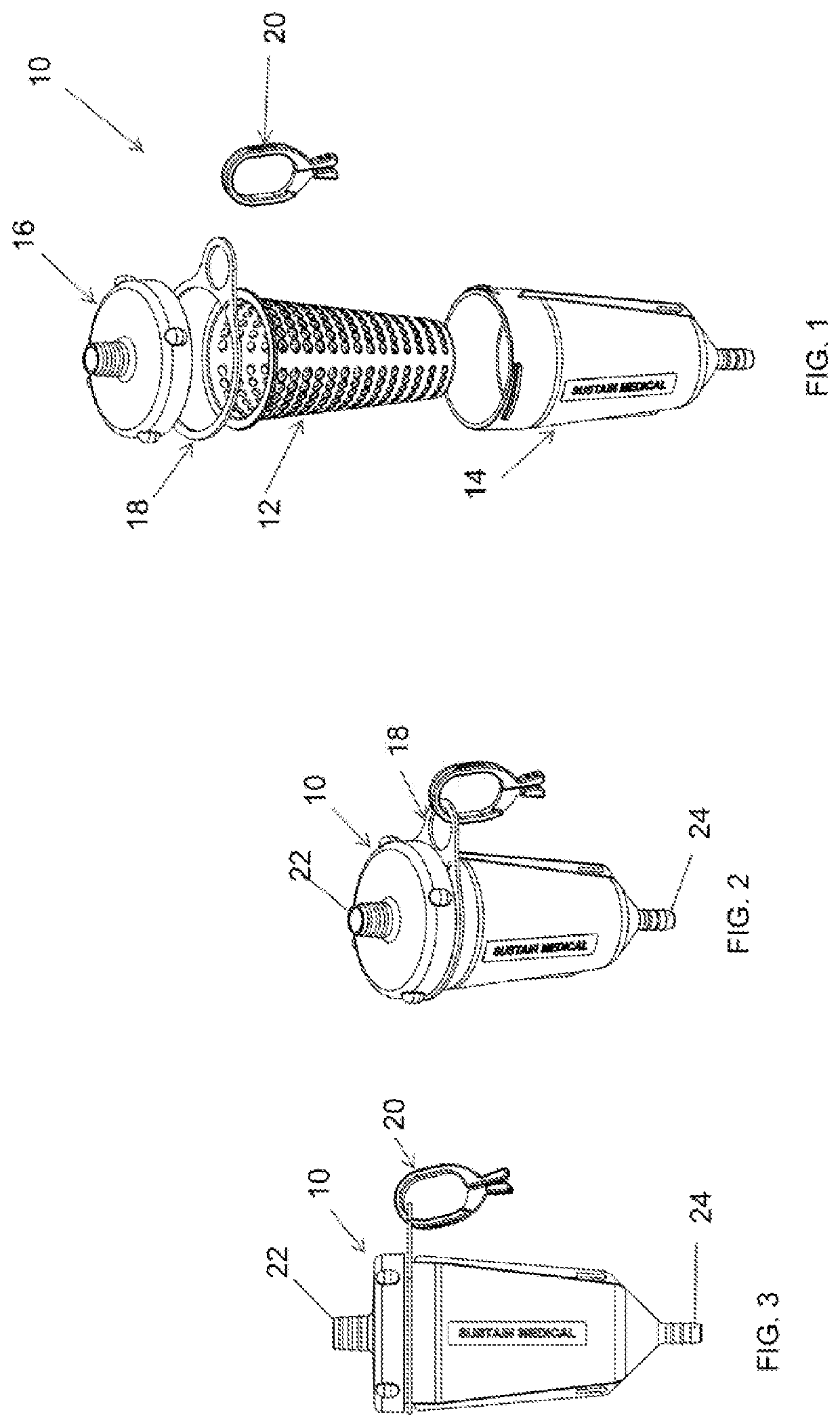
[0035]A filter assembly 10 includes a filter element 12, disposed within container 14 enclosed by a cap 16, as shown in FIGS. 1-3. A support ring 18 is captured between the cap and the container and is configured to receive a clip 20 used to support the filter assembly at the surgical site. The filter assembly includes an inlet tube fitting 22, incorporated into the cap 16, and an outlet tube fitting 24, inc...


PUM

PropertyMeasurementUnit
Lengthaaaaaaaaaa
Lengthaaaaaaaaaa
Lengthaaaaaaaaaa

Abstract

A filter assembly for use with a surgical suction tool for removing fluid and debris from a surgical site includes a conical filter element with a plurality of orifice arrays spaced along the length of the conical body with successively decreasing orifice diameters. The filter element includes an annular flange at the mouth of the filter element that is clamped between a container and a cap. The container includes conically tapered wall to define a radial space between the container and the filter element to permit fluid flow around the filter element and through the container to an outlet tube fitting. A cap covers the mouth of the container with a threaded interface defined between the cap and the container. The threaded interface includes a dual pitch triple lead thread with a coarse lead-in pitch and a fine trailing pitch.

Description

BACKGROUND[0001]The present disclosure relates to surgical filters, and particularly to filters for use in suctioning blood, biological materials and waste matter from a surgical site.[0002]In orthopaedic surgical procedures it is common to apply suction to the surgical site to remove blood, irrigation fluid and debris as needed for visibility of the anatomy at the site. In many cases, the debris can include bone material, surgical cement and soft tissues that can clog the suction apparatus and the path to the waste receptacle. Consequently, it is common to incorporate a filter in the flow path from the suction tool to the waste receptacle. More specifically, the filter is integrated into the flexible tubing running from the suction tool or wand to the waste receptacle.[0003]One problem with in-line filters of this type is that they are prone to blockage from surgical debris, such as large bone pieces. In particular, the small openings or pores of the filter element can be blocked b...

Claims


Application Information

Patent Timeline
IPC IPC(8): A61M1/00B01D46/24B01D46/00
CPCB01D2279/00B01D46/2403B01D2265/029B01D46/0005A61M1/0056B01D46/0004B01D2275/201B01D2275/30A61M1/79
Inventor LINTULA, ERIC
Owner SUSTAIN MEDICAL LLC
Why Eureka
Try Eureka