
Modular illumination system

Inactive Publication Date: 2007-12-20
KOREN PINHAS PAUL
View PDF11 Cites 3 Cited by
  • Summary
  • Abstract
  • Description
  • Claims
  • Application Information

AI Technical Summary

Benefits of technology

[0006] A modular LED lighting assembly generally used as decorative illumination in and/or around residences and businesses is disclosed. A modular light system is disclosed having a distribution panel and a light emitter connected to an output end of the distribution panel. A controller connected to an inpu

Problems solved by technology

If a light, or light emission device, is detached, such as by cutting it, from a wire connecting it to a power source and / or light source, to simply replace the light emission device, not enough wire is typically available to connect the new light emission device to the existing wire because of the precise cut length of the wire.
Furthermore, because of the limited access space that may be provided in its application, replacing a defective wire can be expensive and time consuming.
Additionally, many light systems are limited to a single controller that has a single LED that may then provide light to a plurality of fiber optic strands.
Under such an approach if a controller fails, the complete system, all strands and / or LEDs illuminated by the controller are not able to function.
Furthermore, because fiber optic strands are flexible, depending on conditions that may be experienced by the strands when used in a lighting application, the strands may break or become dislodged.

Method used


Image

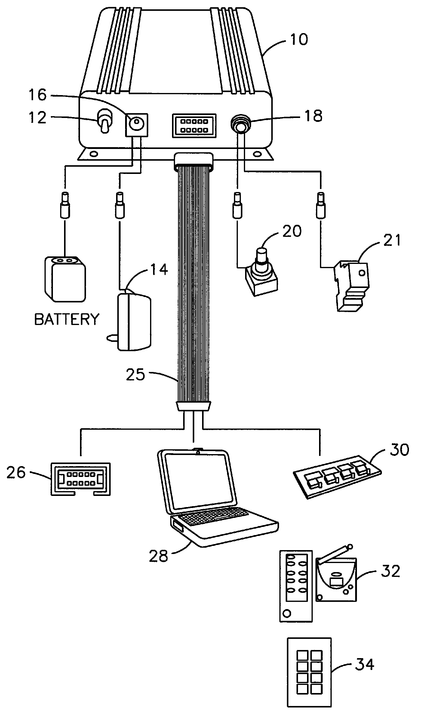
  • Modular illumination system
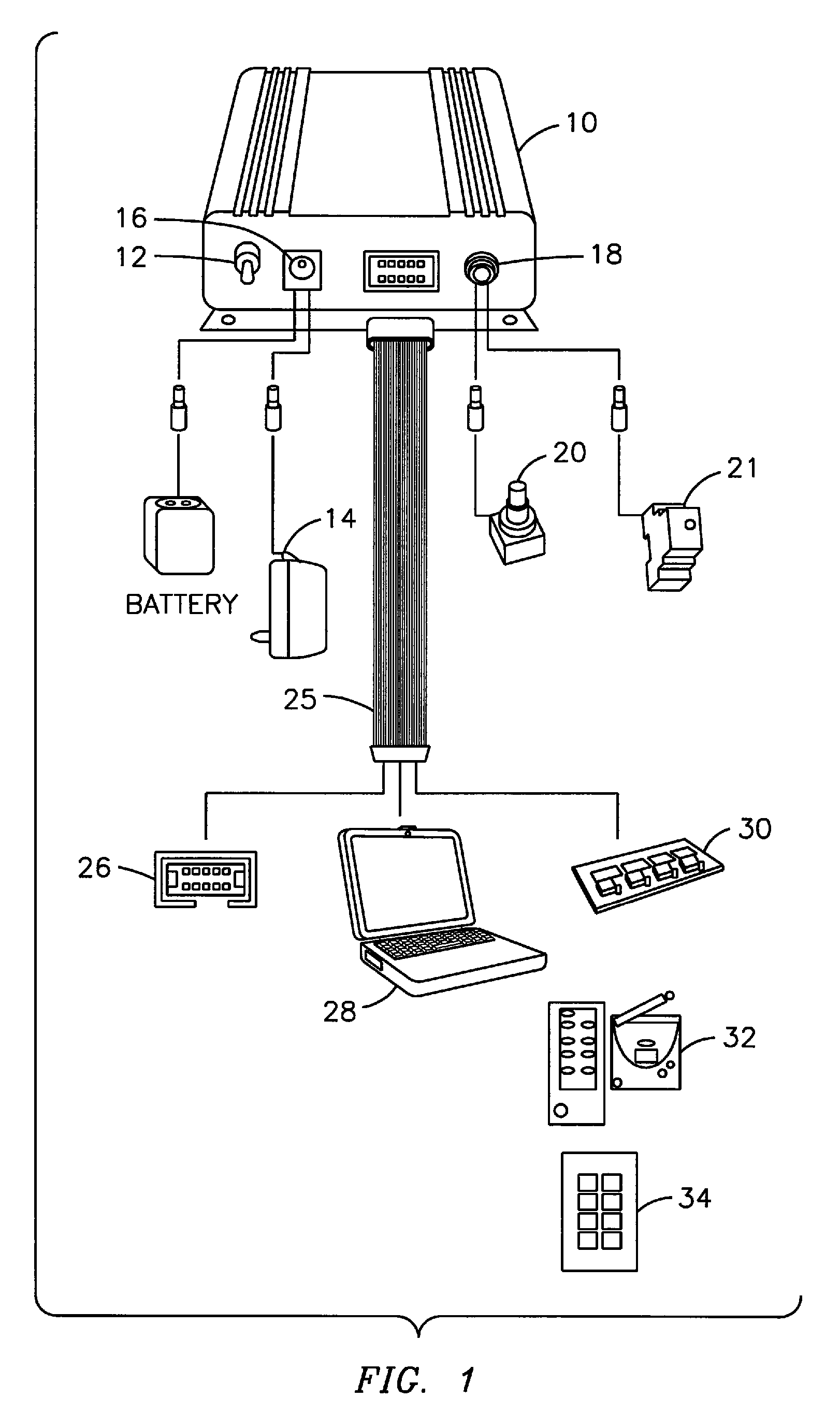
  • Modular illumination system
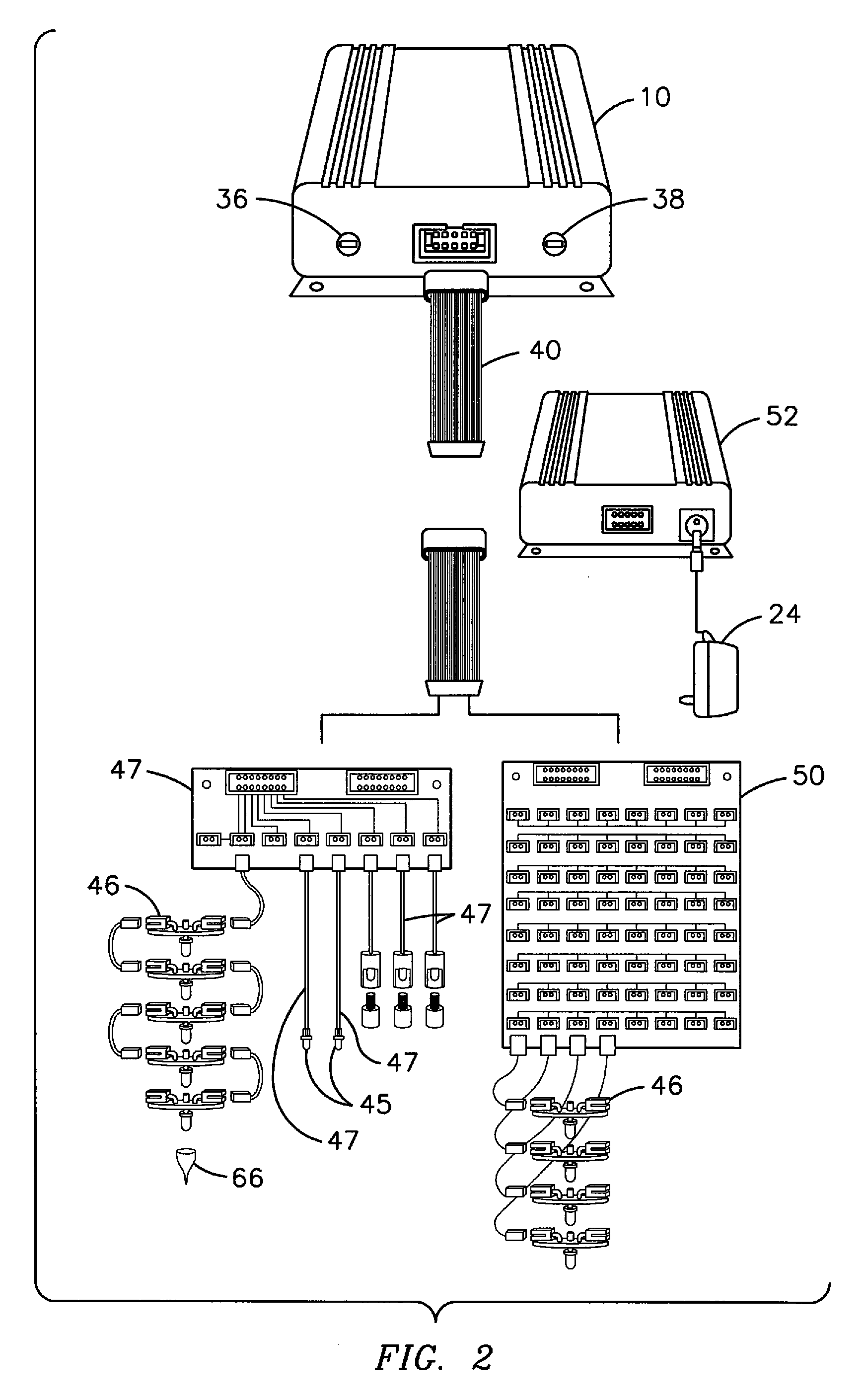
  • Modular illumination system

Examples


Embodiment Construction

[0015] With reference to the figures, exemplary embodiments of the invention will now be described. The scope of the embodiments disclosed is applicable to a plurality of uses. Thus, even though embodiments are described specifically to decorative lighting for residences and businesses, the embodiments are also applicable for other uses or applications where wiring for a light system is run around a hard-to-reach-location, and an opening for the resulting light emitted is smaller than the light emitter, specifically the LED.

[0016] By residential and business uses, this may include but is not limited to architectural lighting such as interior and exterior lighting of residential homes, office complexes and / or other buildings. Similarly, the same or other embodiments may be used in landscaping, such as illuminating sidewalks, pools of water, waterfalls or any other area that needs to be illuminated, including underwater applications.

[0017] Furthermore, though the present invention i...


PUM


Abstract

A modular light system, the system including a distribution panel, a light emitter connected to an output end of the distribution panel, a controller connected to an input end of the distribution panel, a power source connected to said controller, and a harden cap configured to fit around an illumination part of the light emitter at a first end and emits light from a second end that is decreased in diameter when compared to the first end.

Description

CROSS-REFERENCE TO RELATED APPLICATION [0001] This application claims priority based on U.S. Provisional Application No. 60 / 804,974 filed Jun. 16, 2006.FIELD OF INVENTION [0002] The field of invention relates to light emitting diode (LED) technology, and more particularly to a modular LED lighting assembly generally used as decorative illumination in and / or around residences and businesses. BACKGROUND OF THE INVENTION [0003] LED lighting systems are becoming more used for illuminating signs and providing decorative illumination in and / or around residences and businesses. In most circumstances where such lighting systems are used, the light, or light emission device, and wire are permanently affixed to each other. If either the wire or light fails individually, both must be replaced. If a light, or light emission device, is detached, such as by cutting it, from a wire connecting it to a power source and / or light source, to simply replace the light emission device, not enough wire is ...

Claims


Application Information

Patent Timeline
IPC IPC(8): H05B41/36
CPCF21V3/04F21V17/04H05B33/0857H05B33/0803H05B33/0842F21Y2101/02F21Y2115/10H05B45/20H05B45/00
Inventor KOREN, PINHAS PAUL
Owner KOREN PINHAS PAUL
Learn More