Method for Manufacturing Engine Poppet Valve

Active Publication Date: 2021-09-02
NITTAN CORP
View PDF0 Cites 1 Cited by
  • Summary
  • Abstract
  • Description
  • Claims
  • Application Information

AI Technical Summary

Benefits of technology

[0029]Because at least some embodiments of the method for manufacturing an engine poppet valve make it possible to freely manufacture stepped engine valves of different shapes involving change in the length in the stem direction of a second stem portion and/or relative height of a main body portion at a first stem portion and a second stem portion from a single configuration of an intermediate member at an engine valve having a stem portion, a neck portion, and a valve head portion which is formed from a single set of multiple special-purpose dies, and because in accordance with at least some embodiments the neck portion and the second stem portion can be formed by forging such that only the first stem portion is decreased in diameter, without the need to prepare multiple sets of multiple special-purpose dies for each different configuration of stepped engine valve, in accordance with at least some embodiments an intermediate member can be formed more cheaply and varied and diverse engine poppet valves can be manufactured at lower cost than would be the case were the entirety of the intermediate member which includes the neck portion and the second stem portion to be formed by decreasing the diameter of rod stock.
[0030]In accordance with at least one embodiment of the method for manufacturing an engine poppet valve, the fact that the procedure for forming hole(s) at the bottom face of the valve head portion and the sealing procedure involving joining of a cap that would otherwise be carried out are made unnecessary, and the fact that the high-cost/high-precision procedure by which the cap would otherwise be joined thereto and the cutting procedures to increase the precision with which the cap joint portion at the bottom face of the valve would otherwise be finished are made unnecessary, make it possible to manufacture a hollow poppet valve for an engine at low cost. Furthermore, in accordance with at least one embodiment, the fact that a plurality of rollers for carrying out rolling simultaneously cause formation of a stem portion of slender girth and small outside diameter and a first hollow portion of small inside diameter makes it possible to manufacture a long-stemmed hollow poppet valve for an engine at low cost by carrying out a small number of operations. Furthermore, in accordance with at least one embodiment, whereas forming holes multiple times from location(s) toward the valve head portion as is done in accordance with some approaches to form, in continuous fashion, a first hollow portion and a second hollow portion of differing inside diameters causes formation of a step at the connecting portion and occurrence of concentration of stress, because in accordance with a manufacturing method in accordance with at least one embodiment of the present invention the

Problems solved by technology

This being the case, there has been the disadvantage that because dies are expensive, the new set of dies that must be manufactured each time that a new stepped engine valve of different shape is to be formed has caused dramatic increase in engine valve manufacturing cost.
At the diameter-decreasing operation, application at the intermediate stem portion from a base end portion of compressive forces which are inwardly directed in a radial direction from the compressing surfaces of the respective diameter-decreasing tools which have been made to come in contact with a part of the intermediate stem portion that has been made to rotate while being displaced in relative fashion in a d

Method used


Image

  • Method for Manufacturing Engine Poppet Valve
  • Method for Manufacturing Engine Poppet Valve
  • Method for Manufacturing Engine Poppet Valve

Examples


Embodiment Construction

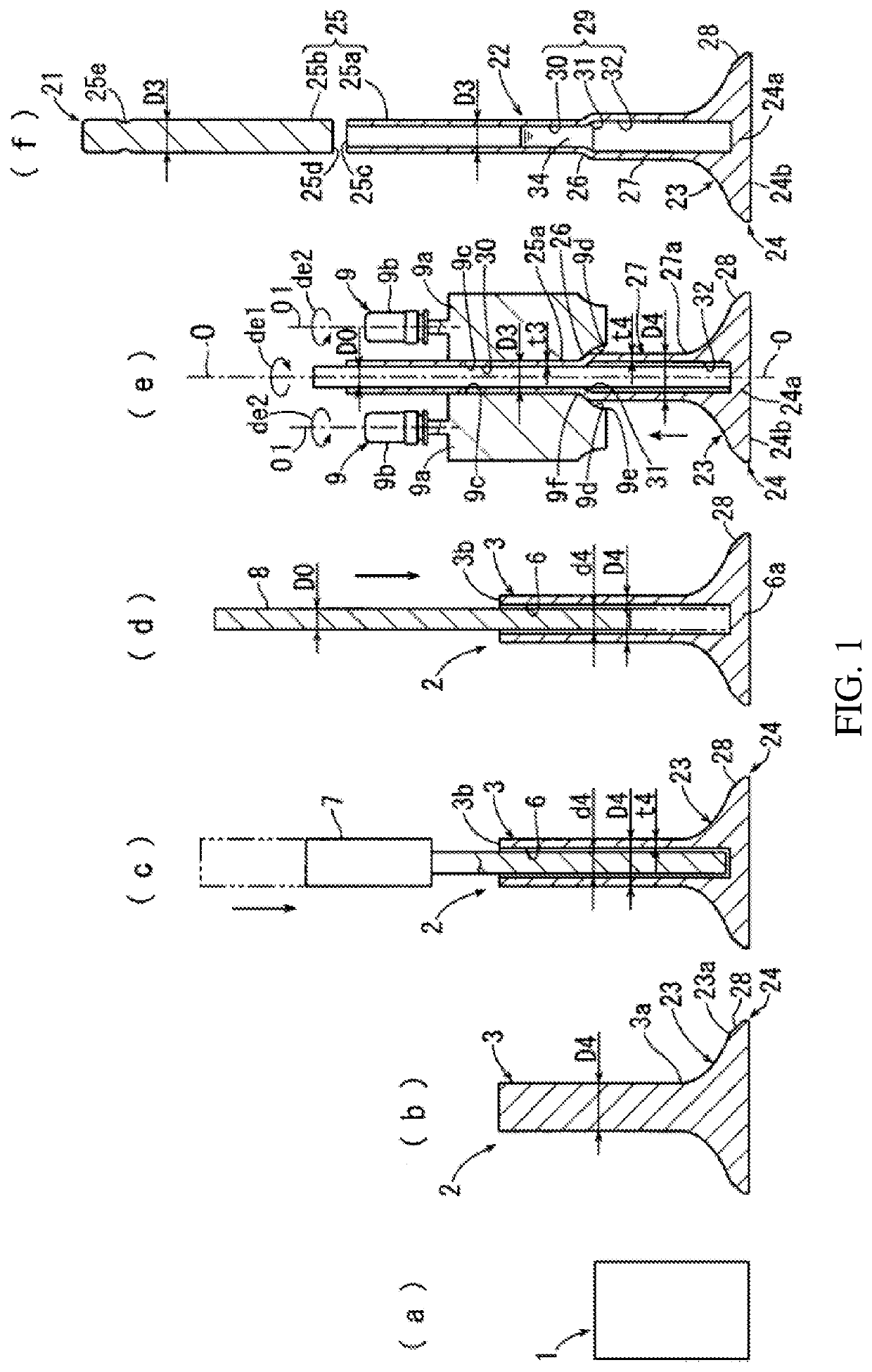
[0041]A first working example of a method for manufacturing a coolant-filled hollow poppet valve for an engine that employs a rolling operation at a diameter-decreasing operation will be described in accordance with FIG. 1. At FIG. 1, in describing a hollow poppet valve for an engine, the side toward valve head portion 24 is taken to be the tip end thereof, and the side toward first stem portion 25 is taken to be the base end thereof.

[0042]Metal rod 1 at (a) in FIG. 1 is formed from rod stock comprising an alloy or the like having high heat resistance such as SUH35 (a martensitic steel having high heat resistance and based on chrome and silicon and / or carbon) which is of high heat resistance. Forging operations are employed to cause metal rod 1 to be made into intermediate member 2 of shape such that valve head portion 24, neck portion 23, and intermediate stem portion 3 shown at (b) in FIG. 1 are formed in integral fashion. Intermediate member 2 may be formed by causing metal rod 1...


PUM

PropertyMeasurementUnit
Electrical resistanceaaaaaaaaaa
Pressureaaaaaaaaaa
Angular velocityaaaaaaaaaa

Abstract

A method for manufacturing an engine poppet valve may comprise a forging operation, a diameter-decreasing operation, and a joining operation. At the forging operation, an intermediate member at which a valve head portion and an intermediate stem portion are made integral by way of a neck portion may be formed. At the diameter-decreasing operation, the intermediate stem portion may be inserted between/among a plurality of diameter-decreasing tools that have stem member compressing surfaces and stem member inlet surfaces formed so as to be progressively distant from the stem member compressing surfaces and toward the tip end and that are arranged at a plurality of circumferentially equipartite locations about a circumference of the intermediate stem portion, application at the intermediate stem portion from a base end portion of compressive forces which are inwardly directed in a radial direction from the compressing surfaces of the respective diameter-decreasing tools which have been made to come in contact with a part of the intermediate stem portion that has been made to rotate while being displaced in relative fashion in a direction along a central axis thereof causing the part of the intermediate stem portion to be decreased in diameter from the base end portion and causing a main body portion of a first stem portion to be formed at the intermediate member and also causing formation by the compressing surfaces of a stepped portion which is continuous with the main body portion, and formation, by an absence of decrease in diameter of a remaining portion at the intermediate stem portion, of a second stem portion which is broader in girth than the main body portion and which is continuous with the neck portion and which is also continuous with the main body portion by way of the stepped portion. At the joining operation, a stem end member having a same outside diameter as the main body portion may be joined to a base end portion of the main body portion.

Description

CROSS-REFERENCE TO RELATED APPLICATION, BENEFIT CLAIM, AND INCORPORATION BY REFERENCE[0001]This application is a continuation-in-part of and claims benefit under 35 USC 120 and 365(c) to copending International Application No. PCT / JP2018 / 041807, entitled “Method for Manufacturing Engine Poppet Valve”, filed 11 Dec. 2018, the content of which is incorporated herein in its entirety by reference.FIELD OF THE INVENTION[0002]Art related to a method for manufacturing an engine poppet valve having a valve head portion and a stem portion made integral by way of a neck portion that increases in diameter as one proceeds toward the tip end.BACKGROUND[0003]One type of engine poppet valve is of such shape that a stem portion and a valve head portion are made integral by way of a neck portion which increases in diameter as one proceeds toward the tip end. Furthermore, one type of poppet valve is a stepped poppet valve in which the stem portion is formed so as to be of step-like shape, the outside...

Claims


Application Information

Patent Timeline
IPC IPC(8): F01L3/20B21K1/22
CPCF01L3/20F01L2303/00B21K1/22F01L3/18F01L3/02F01L3/14F01L2303/01F01L3/10F01L3/08B23P15/002B21J7/16B21D22/16B21H7/00B21H1/18
Inventor KUNITAKE, KOJISATO, DAIKISASAGAWA, YUKI
Owner NITTAN CORP
Why Eureka
Try Eureka