System and method for reductant injection

Active Publication Date: 2015-03-19
CATERPILLAR INC
View PDF6 Cites 0 Cited by
  • Summary
  • Abstract
  • Description
  • Claims
  • Application Information

AI Technical Summary

Benefits of technology

The patent describes a mixing chamber for an exhaust system of an engine that is designed to mix a fluid with exhaust gas. The mixing chamber has a tapering shape, with a first end having a larger cross-sectional area than the second end. The second end is designed to receive an injector. The mixing chamber has two exhaust conduits that form flow paths for the exhaust gas to flow through in a spiral pattern around the chamber's longitudinal axis. The fluid is injected into the flow of exhaust gas at the second end of the mixing chamber. The exhaust gas flows out of the chamber in opposite directions to the direction of flow of the fluid. The technical effects of this design include improved mixing of the fluid and exhaust gas, reduced back pressure on the engine, improved engine performance, and improved emissions control.

Problems solved by technology

This blockage of the passages may affect the efficiency of the mixer.

Method used


Image

  • System and method for reductant injection
  • System and method for reductant injection
  • System and method for reductant injection

Examples


Embodiment Construction

[0011]Reference will now be made in detail to specific embodiments or features, examples of which are illustrated in the accompanying drawings. Generally, corresponding or similar reference numbers will be used, when possible, to refer to the same or corresponding parts.

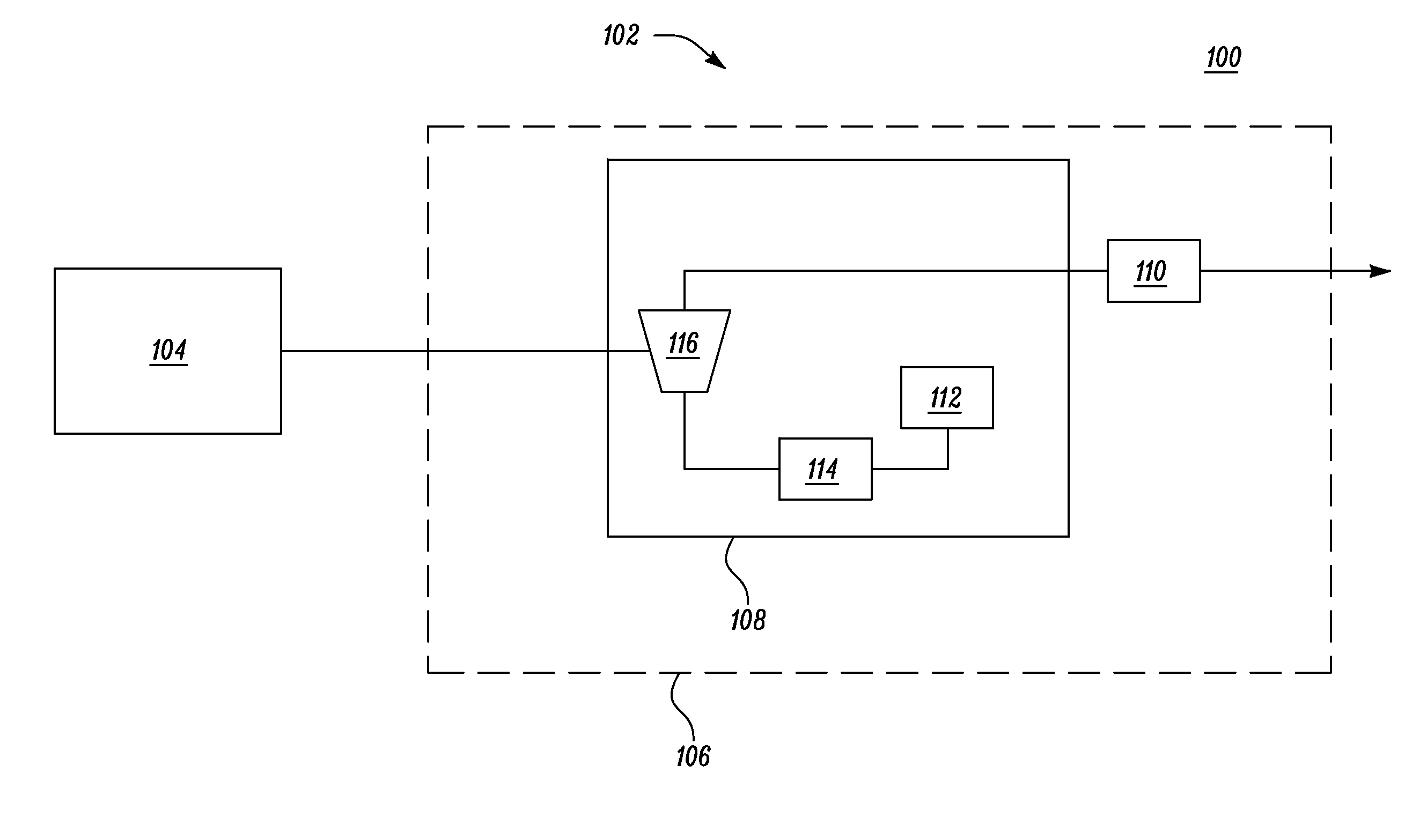
[0012]Referring to FIG. 1, a block diagram 100 of an exemplary engine system 102 is illustrated. The engine system 102 includes an engine 104. In one embodiment, the engine 104 includes a diesel powered engine. In other embodiments, the engine 104 may include any internal combustion engine known in the art including, but not limited to, a gasoline powered engine, a natural gas powered engine or a combination thereof. The engine 104 may include other components (not shown) such as a fuel system, an intake system, a drivetrain including a transmission system and so on. The engine 104 may be used to provide power to any machine including, but not limited to, an on-highway truck, an off-highway truck, an earth moving mac...


PUM


Abstract

A mixing chamber for an exhaust system is disclosed. The mixing chamber includes a tapering cross sectional area perpendicular to a longitudinal axis of the mixing chamber. The mixing chamber includes a first end having a first cross sectional area and a second end having a second cross sectional area. The second cross sectional area is less than the first cross sectional area. The second end is configured to receive an injector. The mixing chamber includes a first exhaust conduit fluidly connected to the first end of the mixing chamber and defining a first exhaust gas flow path into the mixing chamber substantially perpendicular to the longitudinal axis. The mixing chamber also includes a second exhaust conduit fluidly connected to the first end of the mixing chamber and defining a second exhaust gas flow path out of the mixing chamber substantially in the direction of the longitudinal axis.

Description

TECHNICAL FIELD[0001]The present disclosure relates to a system and method for reductant injection, and more specifically to a mixing chamber for reductant injection.BACKGROUND[0002]Mixers are used in engine aftertreatment systems for mixing of two or more fluids. The fluids may include an exhaust gas of an engine and a reductant for treating or reducing one or more constituents of the exhaust gas. A mixer may provide a swirl effect, turbulence or any other mixing effect to provide a uniform mixing of fluids. During the mixing, the fluid such as the reductant may contact and form deposits on the surface of the mixer. After prolonged use, the reductant deposits may block channels and / or passages provided in the mixer. This blockage of the passages may affect the efficiency of the mixer.[0003]U.S. Published Application Number 2011 / 0308234 discloses a dosing and mixing arrangement. The arrangement includes a mixing tube having a constant diameter along its length. At least a first port...

Claims


Application Information

Patent Timeline
IPC IPC(8): F01N3/05
CPCF01N3/05F01N3/208F01N2240/20F01N2610/02F01N2610/1453Y02T10/12
Inventor CHAVANNAVAR, PRAVEEN S.
Owner CATERPILLAR INC
Why Eureka
Try Eureka