Telescopic antenna mast

a technology of telescopic antennas and masts, which is applied in the direction of antennas, lifting devices, and antenna adaptation in movable bodies, etc., can solve the problems of limited propagation of electromagnetic radiation in the microwave frequency range, limited communication maximum range, and adverse effects on communication, so as to increase the height of the antenna, increase the range of effective communications, and maximize the available antenna height of the antenna mast

Inactive Publication Date: 2020-04-09
DOMINGUEZ EDDY
View PDF0 Cites 0 Cited by
  • Summary
  • Abstract
  • Description
  • Claims
  • Application Information

AI Technical Summary

Benefits of technology

The patent describes a cellular communication system that includes a modular shelter with pre-configured equipment, a door, a computer rack, a radio unit rack, air conditioning, and an antenna system. The antenna system includes a base section with a plurality of movable antenna sections that can be extended to overcome obstructions in the environment. The system increases the range of effective communications between the vehicle or fixed base and a remotely located communication device. The advantages of the system are economical, practical, and easy to use.

Problems solved by technology

However, if the mast is too short, communications may be adversely affected because of obstructions in the environment.
The limitation in height of the antenna may limit the maximum range of effective communications between the vehicle and a communications device located remotely apart from the vehicle.
For example, electromagnetic radiation that is in the microwave frequency range may be limited to propagation in line-of-sight paths or may be severely attenuated by ground clutter where antenna height is insufficient for a requisite level of clearance.

Method used


Image

  • Telescopic antenna mast
  • Telescopic antenna mast
  • Telescopic antenna mast

Examples


Embodiment Construction

[0023]The following description is of the best-contemplated mode of carrying out the invention. This description is made for the purpose of illustrating the general principles of the invention and should not be taken in a limiting sense. The scope of the invention is best determined by reference to the appended claims.

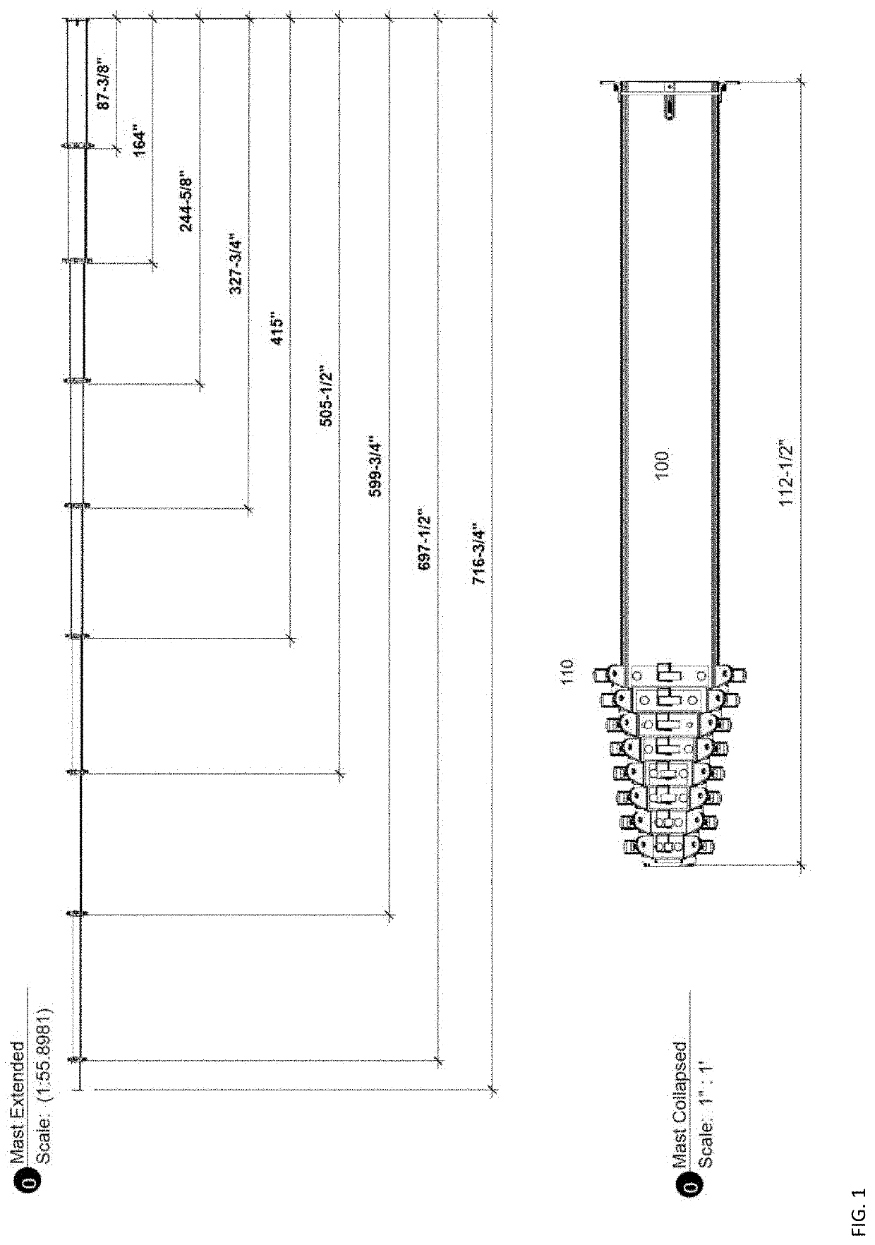
[0024]FIG. 1 shows an extendable antenna mast which telescopically extends the height of the antenna to maximize radio communication range in the extended configuration during operation and to minimize space in a collapsed configuration when the antenna is being transported. As shown in FIG. 1, the collapsed configuration has a base unit 100 with a plurality of extension heads 110 on respective extended stages, each of which can be locked with pins to secure each extended stage. Once the locking pins are inserted, the stage cannot be collapsed, thus increasing support and safety for operators. In the collapsed configuration, the entire mast can be as short as 112½″ in ...


PUM


Abstract

An antenna system includes a base section; a plurality of movable antenna sections adapted to fit inside of the base section, each movable antenna section including an outside section and an inside section, wherein the outside section has a plurality of section locks penetrating through the inside and outside sections; and a lock pin to prevent the inside section from collapsing into the outside section in an extended mode.

Description

FIELD OF THE INVENTION[0001]This invention relates to a telescopic antenna mast.BACKGROUND OF THE INVENTION[0002]An antenna mast may be mounted on a building or a vehicle to support the mounting of antenna. The antenna may be used for reception, transmission or both reception and transmission of an electromagnetic signal. Ideally, the antenna should be as high as possible to optimum signal transmission or reception. However, in certain mobile, vehicular, or temporary antenna base stations demand a short device for ease of transportation. However, if the mast is too short, communications may be adversely affected because of obstructions in the environment. Obstructions may include vegetation, vine canopies, tree canopies, bridges, traffic signals, buildings or otherwise. The limitation in height of the antenna may limit the maximum range of effective communications between the vehicle and a communications device located remotely apart from the vehicle. For example, electromagnetic ra...

Claims


Application Information

Patent Timeline
Patent Type & Authority Applications(United States)
IPC IPC(8): H01Q1/12B66F3/46H01Q1/32
CPCB66F3/46H01Q1/3216H01Q1/1235H01Q1/246
Inventor DOMINGUEZ, EDDY
Owner DOMINGUEZ EDDY
Why Eureka
Try Eureka