
Method and system for providing transparent communication

a communication system and communication system technology, applied in the field of communication system and a communication system, can solve the problems of affecting the safety of the managed traffic system, and many telecommunication providers no longer offering analog landlines

Active Publication Date: 2020-04-16
ROHDE & SCHWARZ GMBH & CO KG
View PDF0 Cites 1 Cited by
  • Summary
  • Abstract
  • Description
  • Claims
  • Application Information

AI Technical Summary

Benefits of technology

The patent text describes a communication system that uses keep-alive messages and the detection of a failure of the main radio unit to provide a reliable way of detecting failures in the system. This means that even if the standby radio unit fails, another unit can take over and ensure continued communication, improving the security of the system against failures. The system can also be based on existing data protocols and can be expanded or updated easily to implement a communication system according to the present invention.

Problems solved by technology

However, many telecommunication providers no longer offer analog landlines.
If the main radio unit fails or provides a radio link of poor quality a switchover from the main radio unit to the standby radio unit has to take place.
However, in a conventional communication system, switching from the main radio unit to the standby radio unit can cause an interruption in the communication between the user console and the mobile radio unit.
The interruption of the communication between the mobile radio unit and the user console can have severe impacts on the safety of the managed traffic system.
Even if the interruption of the voice communication between an air pilot and an air traffic controller is relatively short, this may lead to misunderstandings or suppression of relevant traffic information which may cause catastrophic air accidents.

Method used


Image

  • Method and system for providing transparent communication
  • Method and system for providing transparent communication
  • Method and system for providing transparent communication

Examples


Embodiment Construction

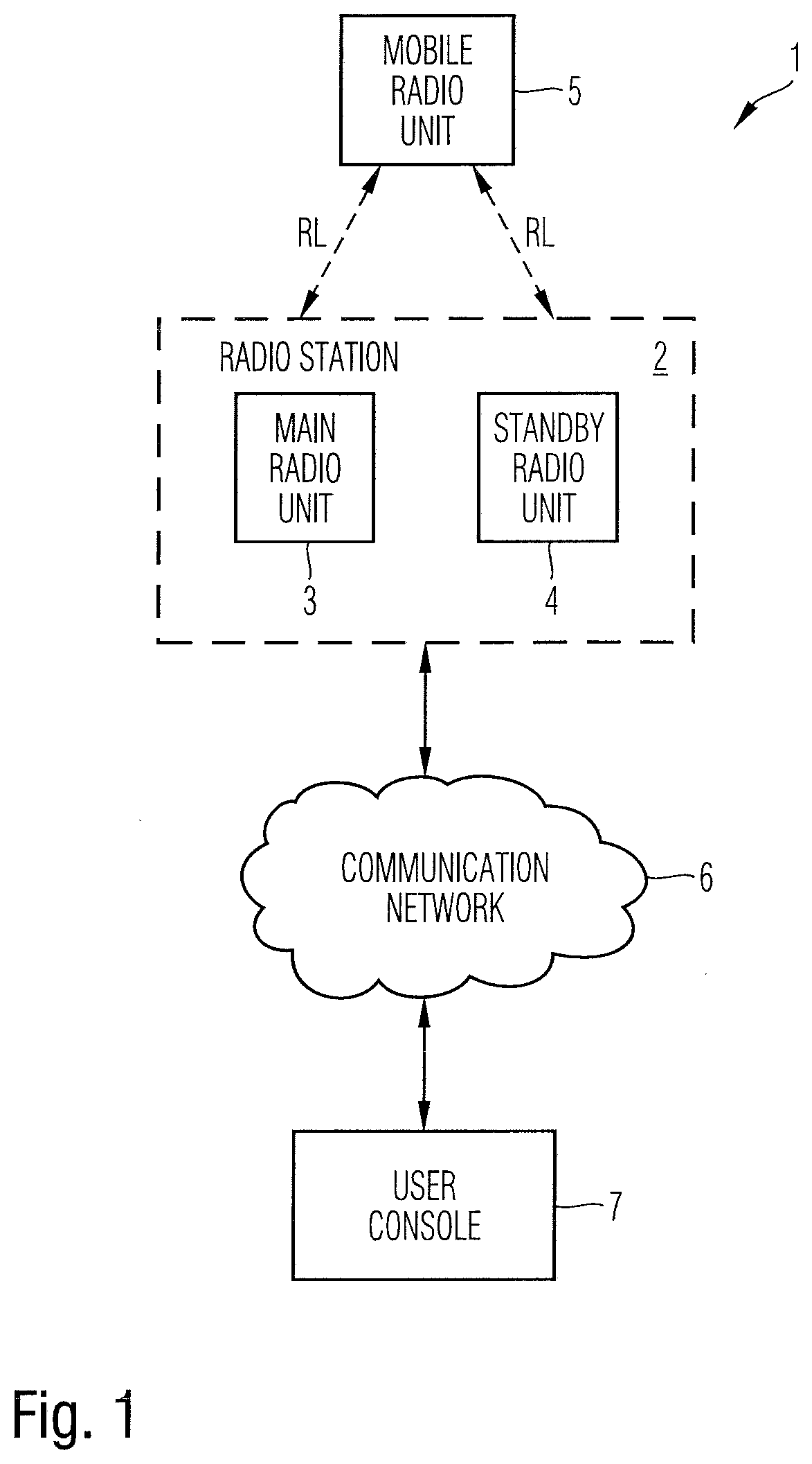
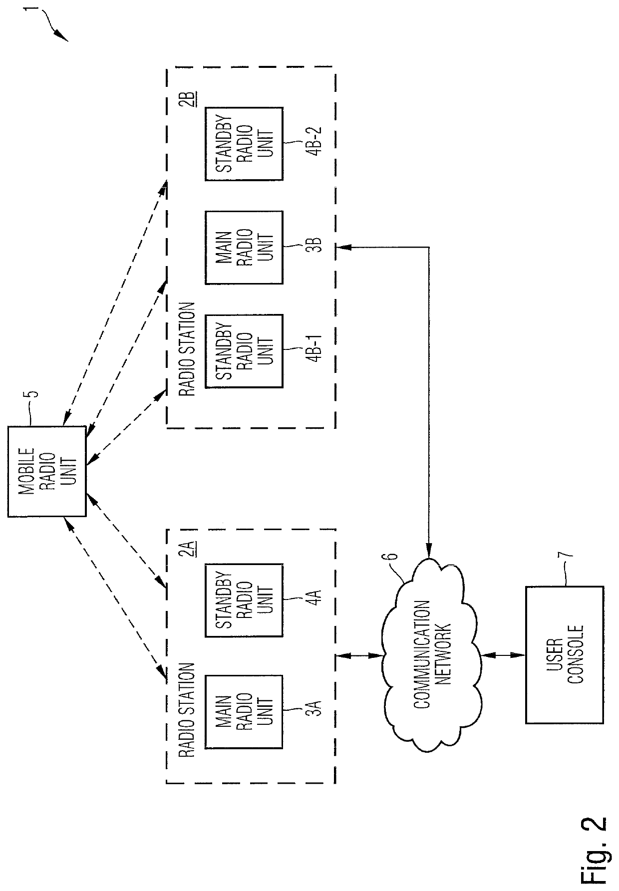
[0043]As can be seen in the block diagram of FIG. 1, the communication system 1 according to the first aspect of the present invention comprises at least one radio station 2 which includes a main radio unit 3 and at least one associated standby radio unit 4. In the illustrated embodiment of FIG. 1, the radio station 2 comprises a single main radio unit 3 and a single standby radio unit 4. In other possible embodiments, the radio station 2 may comprise more than one standby radio units 4. The main radio unit 3 and the standby radio unit 4 can both establish a radio link RL with a mobile radio unit 5 as shown in FIG. 1. The mobile radio unit 5 can be integrated or attached to a vehicle such as a car or an aircraft. As shown in FIG. 1, the radio station 2 is connected via a communication network 6 to a user console 7. The user console 7 is connected via the communication network 6 to the main radio unit 3 of the radio station 2 addressed by a network address of the communication networ...


PUM


Abstract

A communication system comprising at least one radio station which includes a main radio unit and at least one associated standby radio unit and comprising a user console connected via a communication network to the main radio unit of the radio station addressed by a network address of the communication network, wherein the main radio unit and its associated standby radio units are configured to be operated in parallel and to exchange operational parameters during operation of said communication system, wherein an operation failure of the main radio unit of a radio station triggers an automatic handover of the used network address from the main radio unit of the radio station to an associated standby radio unit of said radio station to maintain an uninterrupted communication between the user console and the respective radio station of said communication system.

Description

CROSS REFERENCE TO RELATED APPLICATION[0001]This application claims priority to European Patent Application No. 18200740.1, filed on Oct. 16, 2018, the content of which is hereby incorporated by reference.FIELD OF THE INVENTION[0002]The invention relates to a communication system and a method for providing transparent communication between a user console and a radio station via a communication network.TECHNICAL BACKGROUND[0003]Voice communication systems (VCSs) can be used for handling different kinds of traffic via radio links. For example, air traffic control systems (ATC) can comprise voice communication systems used for communication between an air traffic controller and a pilot. All flights based on instrument flight rules IFR require voice communication between the pilot and the air traffic controller. Voice communications can take place based on a radio network that ensures countrywide coverage during all phases of the flight independent of the altitude of the airplane. For t...

Claims


Application Information

Patent Timeline
IPC IPC(8): H04W36/38H04W36/08H04L29/08
CPCH04L67/145H04W36/38H04W36/08H04W24/04H04W88/08H04W36/16
Inventor GUALTIERI, FRANCESCOGANSLMEIER, BERNHARD
Owner ROHDE & SCHWARZ GMBH & CO KG
Learn More