
Semi-automatic shotgun and components thereof

Pending Publication Date: 2022-07-21
SAVAGE ARMS
View PDF0 Cites 0 Cited by
  • Summary
  • Abstract
  • Description
  • Claims
  • Application Information

AI Technical Summary

Benefits of technology

The gas operated semiautomatic shotgun described in this patent has several features that make it better and more reliable than other similar guns. It can handle different types of ammunition more easily and is less recoil. It also requires less cleaning and maintenance and is easier to disassemble and assemble than other guns.

Problems solved by technology

The reliability of the cycling can be affected by the type of shotshell cartridge fired, the maintenance of the shotgun, as well as the wear on components of the shotgun.
And a shotgun that cycles for both a lower powered skeet round and a magnum powered round may subject the cycle mechanism components to higher forces causing premature wear and failure of components or function.
It does not however, strictly speaking, gauge the energy of the cartridge.
While in general longer cartridges are typically higher energy, this is not always the case.
Build-up of debris in the gas operating systems can also impact cycling reliability.
Conventional gas operated shotguns bleed gas pressure from the barrel through ports, conventional ports can shave polymer from the cartridge wads causing reliability issues with the gas operating system.
This can be minimized by angling the ports, but this is difficult and expensive in a manufacturing environment.
First, compared to multiple ports at the cartridge chamber, it is believed less energy for propelling the shot is lost at this location as the shot has already reached a high velocity.

Method used


Image

  • Semi-automatic shotgun and components thereof
  • Semi-automatic shotgun and components thereof
  • Semi-automatic shotgun and components thereof

Examples


Embodiment Construction

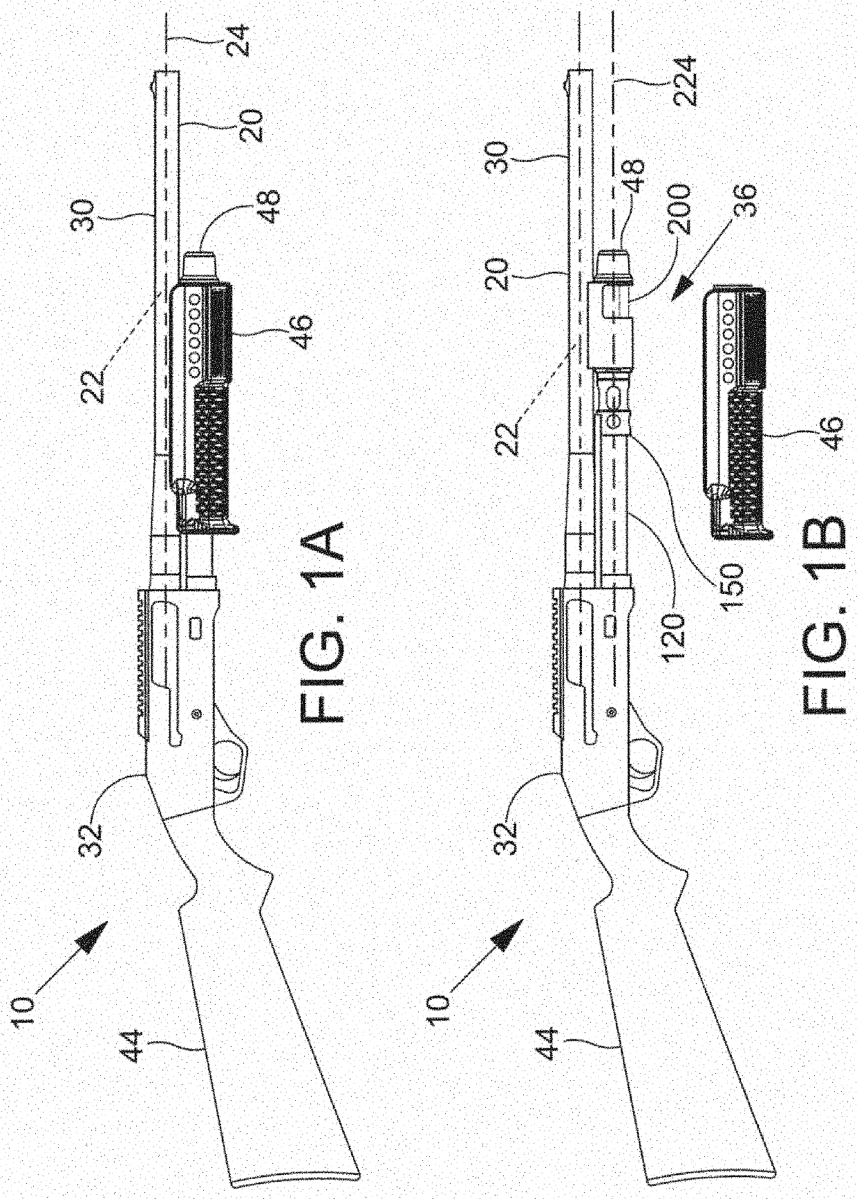
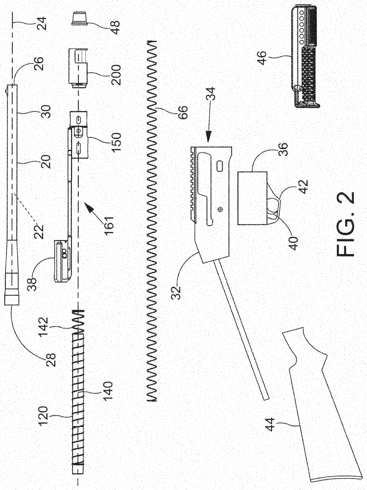
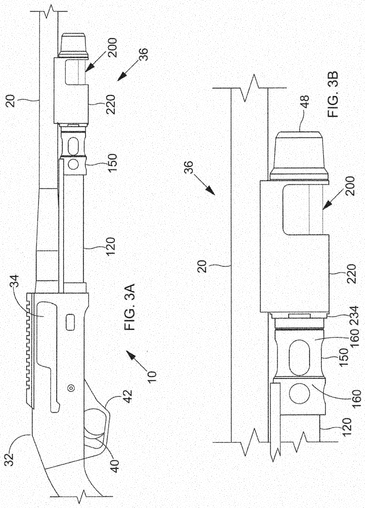
[0118]Referring, for example, to FIGS. 1-3A, a semiautomatic shotgun 10 in accordance with one or more embodiments comprises a receiver 32 defining a receiver interior 34 and a breech block 38 that is slidably received in the receiver interior 34. The breech block 38 is movable between a forward position in which the breech block 38 engages the breech end 28 of the barrel 20 for firing a chambered shell and a rearward position in which the breech block 38 is positioned rearward of the breech end 28 of the barrel 20 for discharging a spent shell. A barrel 20 and a magazine tube 120 extend forwardly from a forward portion of the receiver 32. The barrel 20 has a breech end 28 and a muzzle end 26. A barrel wall 30 of the barrel 20 extends from the breech end 28 to the muzzle end 26. The barrel wall 30 defines a barrel bore 22 extending along a barrel axis 24 of the barrel 20. The barrel wall 30 defines a firing chamber and barrel bore 22, the firing chamber being dimensioned and configu...


PUM


Abstract

A semiautomatic shotgun comprising a receiver, a barrel, a forward gas block assembly attached to the barrel, a slider assembly rearward of the gas block assembly extending into the receiver. Upon firing a shotshell the explosive gases in the barrel are diverted through two ports into the gas block assembly, specifically into a pair of lateral pressure relief valves positioned on both sides of the barrel. The pressure relief valves further having a gas pathway from the barrel provided by clusters of holes less than a specific size and on-center with the barrel axis. A piston is forced rearwardly and engages a slider of the slider assembly that is linked to a breech block in the receiver. The breech block loads unfired shells and ejects the fired shells accomplishing the semiautomatic recycling. The dual pressure relief valves actuate to moderate and limit the gas pressure that enters the piston chamber when using shotshells of different power levels thereby providing consistency in the recycling operation. The shotgun assembled with a plurality of retention pins having uniformly sized O-rings.

Description

CROSS-REFERENCE TO RELATED APPLICATIONS[0001]This application claims priority to U.S. Provisional Application No. 63 / 132,791 filed on Dec. 31, 2021, and is a continuation-in-part to U.S. patent application Ser. No. 17 / 361,573 filed on Jun. 29, 2021, which is a continuation-in-part of U.S. patent application Ser. No. 16 / 506,646, filed Jul. 9, 2019, now U.S. Pat. No. 11,047,635, which is a continuation of U.S. patent application Ser. No. 15 / 847,822, filed Dec. 19, 2017, now U.S. Pat. No. 10,345,062, which claims the benefit of U.S. Provisional Application No. 62 / 436,346, filed on Dec. 19, 2016, the disclosures of which are incorporated by reference herein in their entireties.BACKGROUND OF THE DISCLOSURE[0002]Shotguns of any particular gauge may fire different shotshell cartridges with different payloads and propellant loads. With pump action shotguns the recycling occurs after the firing of the shotshell cartridges and occurs manually. Thus, there is no relation of the type of propell...

Claims


Application Information

Patent Timeline
IPC IPC(8): F41A5/28F41A9/72
CPCF41A5/28F41A9/72F41C7/00F41A3/84
Inventor ALEXANDER, AARON K.LINSCOTT, JOHN
Owner SAVAGE ARMS
Learn More