Variable magnification optical system, optical equipment, imaging equipment and method for manufacturing variable magnification optical system

Active Publication Date: 2020-04-23
NIKON CORP
View PDF0 Cites 0 Cited by
  • Summary
  • Abstract
  • Description
  • Claims
  • Application Information

AI Technical Summary

Benefits of technology

The present invention provides a variable magnification optical system that can change the distance between the first, second, third, and fourth lens groups to achieve desired magnification, and can move the fourth lens group to achieve focus. The system satisfies a conditional expression to achieve sharp image quality. The invention also provides a method for manufacturing the optical system.

Problems solved by technology

However, with respect to conventional variable magnification optical system, weight reducing has not been taken in consideration sufficiently.

Method used


Image

  • Variable magnification optical system, optical equipment, imaging equipment and method for manufacturing variable magnification optical system
  • Variable magnification optical system, optical equipment, imaging equipment and method for manufacturing variable magnification optical system
  • Variable magnification optical system, optical equipment, imaging equipment and method for manufacturing variable magnification optical system

Examples


first example

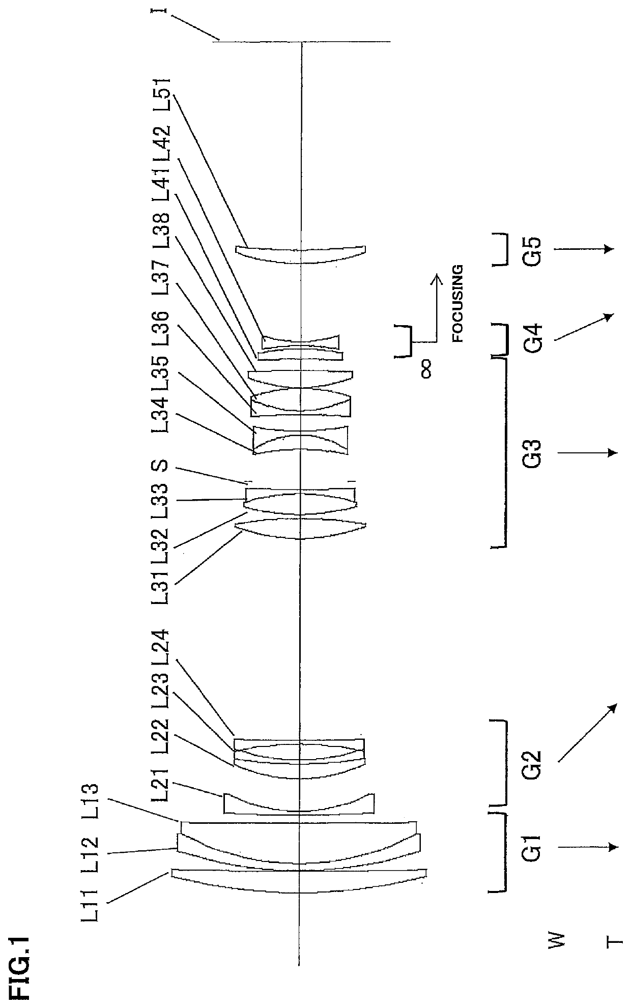
[0067]FIG. 1 is a sectional view, showing the variable magnification optical system according to the First Example. Meanwhile, arrows in FIG. 1 and in FIG. 5, FIG. 9 and FIG. 13 described later show movement trajectories of the respective lens groups upon varying magnification from the wide angle end state (W) to the telephoto end state (T).

[0068]The variable magnification optical system according to the First Example is composed of, in order from an object side, a first lens group G1 having positive refractive power, a second lens group G2 having negative refractive power, a third lens group G3 having positive refractive power, a fourth lens group G4 having negative refractive power and a fifth lens group G5 having positive refractive power.

[0069]The first lens group G1 consists of, in order from the object side, a positive meniscus lens L11 having a convex surface facing the object side, and a cemented positive lens constructed by a negative meniscus lens L12 having a convex surfa...

second example

[0093]FIG. 5 is a sectional view, showing the variable magnification optical system according to the Second Example.

[0094]The variable magnification optical system according to the Second Example is composed of, in order from an object side, a first lens group G1 having positive refractive power, a second lens group G2 having negative refractive power, a third lens group G3 having positive refractive power, a fourth lens group G4 having negative refractive power and a fifth lens group G5 having positive refractive power.

[0095]The first lens group G1 consists of, in order from the object side, a positive meniscus lens L11 having a convex surface facing the object side, and a cemented positive lens constructed by a negative meniscus lens L12 having a convex surface facing the object side cemented with a double convex positive lens L13.

[0096]The second lens group G2 consists of, in order from the object side, a negative meniscus lens L21 having a convex surface facing the object side, ...

third example

[0109]FIG. 9 is a sectional view, showing the variable magnification optical system according to the Third Example.

[0110]The variable magnification optical system according to the Third Example is composed of, in order from an object side, a first lens group G1 having positive refractive power, a second lens group G2 having negative refractive power, a third lens group G3 having positive refractive power, a fourth lens group G4 having negative refractive power and a fifth lens group G5 having positive refractive power.

[0111]The first lens group G1 consists of, in order from the object side, a positive meniscus lens L11 having a convex surface facing the object side, and a cemented positive lens constructed by a negative meniscus lens L12 having a convex surface facing the object side cemented with a double convex positive lens L13.

[0112]The second lens group G2 consists of, in order from the object side, a negative meniscus lens L21 having a convex surface facing the object side, a ...


PUM


Abstract

A variable magnification optical system comprises, in order from an object side, a first lens group G1 having positive refractive power, a second lens group G2 having negative refractive power, a third lens group G3 having positive refractive power and a fourth lens group G4 having negative refractive power; upon varying a magnification, a distance between the first lens group G1 and the second lens group G2 being varied, a distance between the second lens group G2 and the third lens group G3 being varied, and a distance between the third lens group G3 and the fourth lens group G4 being varied; upon focusing, the fourth lens group being moved; and a predetermined conditional expression being satisfied. With such configuration, there is provided a variable magnification optical system whose focusing lens group is compact in size and reduced in weight, so high speed and quiet focusing can be effected without lens barrel being made large in size, and further by which variations in aberrations upon varying magnification from the wide angle end state to the telephoto end state as well as variations in aberrations upon focusing from the infinite distance object to the close distance object can be superbly suppressed.

Description

TECHNICAL FIELD[0001]The present invention relates to a variable magnification optical system, an optical equipment, an imaging equipment, and a method for manufacturing the variable magnification optical system.BACKGROUND ART[0002]Conventionally, there have been proposed a variable magnification optical system which is suitable for a photographing camera, an electronic still camera, a video camera or the like. See, for example, Japanese patent application Laid-Open Gazette No. H4-293007. However, with respect to conventional variable magnification optical system, weight reducing has not been taken in consideration sufficiently.PRIOR ART REFERENCEPatent Document[0003]Patent Document 1: Japanese patent application Laid-Open Gazette No. H4-293007SUMMARY OF THE INVENTION[0004]According to a first aspect of the present invention, there is provided a variable magnification optical system comprising, in order from an object side: a first lens group having positive refractive power, a seco...

Claims


Application Information

Patent Timeline
IPC IPC(8): G02B15/14H04N5/225
CPCG02B9/34G02B15/144105H04N5/2254G02B15/16G02B15/145121H04N23/55
Inventor MACHIDA, KOSUKE
Owner NIKON CORP
Why Eureka
Try Eureka