Apparatus and method for calculating aiming point information

a technology of aiming point and information, applied in the field of target acquisition, can solve the problems of insufficient skill of the shooter and insufficient consistency of ammunition, conventional telescopic target acquisition devices are not generally useful at long ranges in excess of 400-800 yards, and conventional target acquisition devices generally fall short when extreme accuracy is desired

Active Publication Date: 2015-02-24
HVRT CORP
View PDF214 Cites 67 Cited by
  • Summary
  • Abstract
  • Description
  • Claims
  • Application Information

AI Technical Summary

Benefits of technology

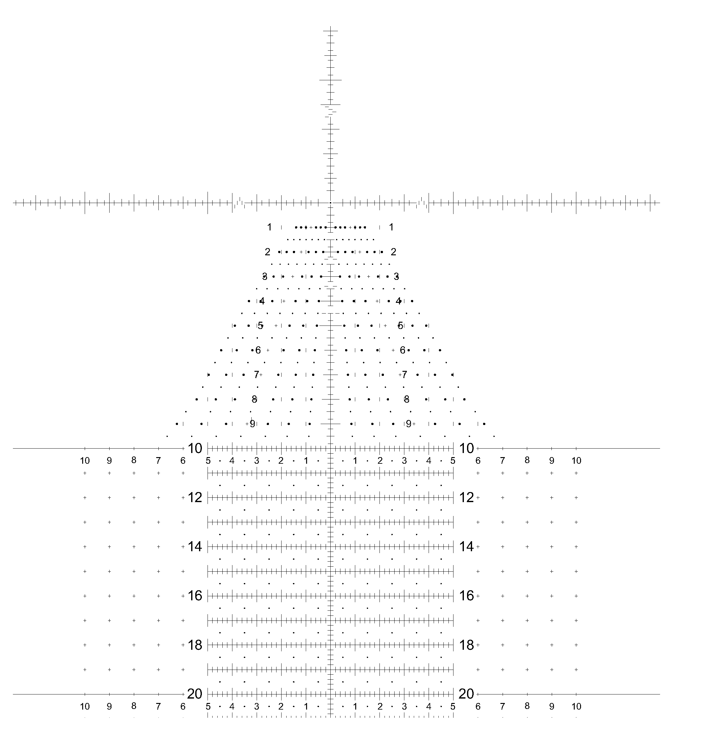
[0006]The present invention provides reticles that provide means for selecting aiming points that accurately target an intended target at any desired range, including extreme distances. In particular, the reticles of the present invention provide markings or other indications that allow a user, for example, to associate a first aiming point of the reticle with an intended target (e.g., the aiming point created by the cross-section of primary vertical and horizontal cross-hairs), and to identify a second aiming point (e.g., identified by a generated aiming dot, an electronic aiming dot, or an aiming point created by secondary vertical and / or horizontal cross-hairs) that represents a point to insure an accurate shot to hit the target.
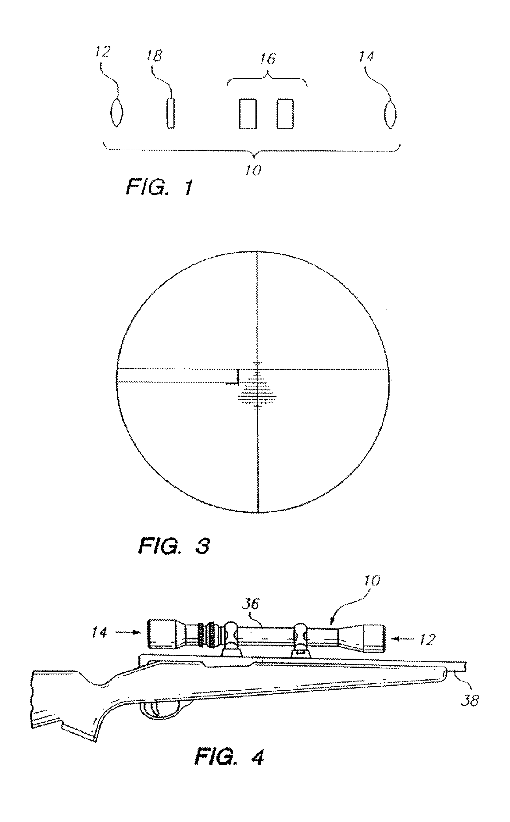
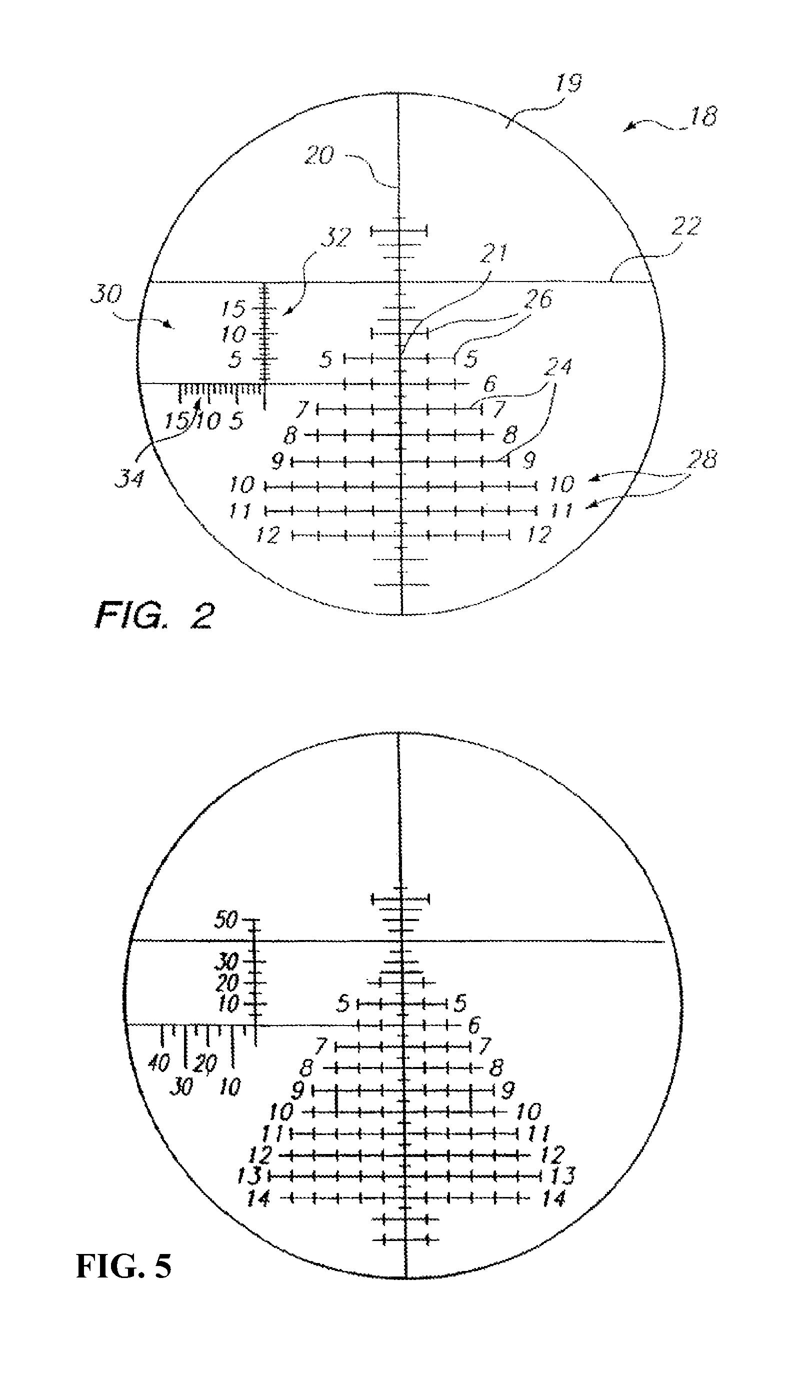
[0010]In a preferred embodiment, reticles of the present invention are constructed from an optically transparent wafer or electronically generated disc having an optical center that coincides with a center of a field of vision when the wafer is mounted in a scope. In one embodiment, a primary vertical cross-hair having a predetermined thickness bisects the disc, intersecting the optical center of the disc, or intersecting at a point offset from the optical center of the disc. In another embodiment, a primary horizontal cross-hair having a predetermined thickness intersects the primary vertical cross-hair, most preferably above the optical center of the disc, to form an upper right sector (e.g., quadrant), an upper left sector, a lower right sector, and a lower left sector. Two or more secondary horizontal cross-hairs having predetermined thickness are spaced along the primary vertical cross-hair. In a particularly preferred embodiment, at least some of these secondary horizontal cross-hairs are identified with a unique identifier, to aid the shooter in calibrating the horizontal cross-hairs by range, and in locating the appropriate horizontal cross-hair to use in selecting an aiming point and to communicate with, for example, a spotter. A plurality of secondary vertical cross-hairs having predetermined thickness and configurations are spaced along at least some of said secondary horizontal cross-hairs to aid in making accurate windage adjustments. In a further embodiment separate range-finding means are positioned on the reticle to aid the shooter in determining the range to target. In a still further embodiment, the shooter uses the distance subtended by the vertical or horizontal lines to calculate the range to the target.
[0011]The reticles of the present invention may be made of any suitable material. The reticles may have any suitable markings that permit use as described above and elsewhere herein. The markings may be generated by any means, including, but not limited to, engravings, etchings, projections, wires, digital or analog imaging, raised surfaces (e.g., made of any desired material), etc. The reticles may be used in any type of device where there is use for secondary or multiple aiming points. The reticles may be used in conjunction with one or more additional components that facilitate or expand use (e.g., ballistic calculators, devices that measure exterior factors, meteorological instruments, azimuth indicators, compasses, chronographs, distance ranging devices, etc.).
[0013]While the reticles of the present invention find use in long-range target acquisition devices they can be used with equal effectiveness at close and medium ranges. In one embodiment, the reticles of the present invention are adapted for use in a mid-range telescopic gunsight, or close range telescopic gunsight, or other device. A mid-range reticle, similar to the long-range reticle described above, is constructed in accordance with this invention. Since the mid-range reticle requires less field area, in some embodiments, the primary horizontal cross-hair can be conventionally positioned at the optical center of the reticle. The mid-range reticle can then be calibrated and used in the same manner as a long-range reticle.
[0014]In yet another embodiment, a portion of the primary vertical cross-hair or the primary horizontal cross-hair, or both, is provided with rangefinder markings to eliminate the need for a separate rangefinder means in one of the sectors formed by the intersection of the primary vertical and horizontal cross-hairs.

Problems solved by technology

At long ranges, for example, in excess of 500 yards, the skill of the shooter and the consistency of the ammunition are often not enough to insure that the shooter will hit the target.
Conventional telescopic target acquisition devices are not generally useful at long ranges in excess of 400-800 yards.
At close ranges less than 100 yards conventional target acquisition devices generally fall short when extreme accuracy is desired.
Modifications to this basic system have not, thus far, enabled a skilled shooter firing at long ranges to acquire and hit a target quickly and reliably, regardless of the weapon used (assuming always that the firearm is capable of reaching a target at the desired long range).

Method used


Image

  • Apparatus and method for calculating aiming point information
  • Apparatus and method for calculating aiming point information
  • Apparatus and method for calculating aiming point information

Examples


Embodiment Construction

[0086]The present invention relates to target acquisition and related devices, and more particularly to telescopic gunsights and associated equipment used to achieve shooting accuracy at, for example, close ranges, medium ranges and extreme ranges at stationary and moving targets. Certain preferred and illustrative embodiments of the invention are described below. The present invention is not limited to these embodiments.

[0087]As used herein, the term “firearm” refers to any device that propels an object or projectile, for example, in a controllable flat fire, line of sight, or line of departure, for example, handguns, pistols, rifles, shotgun slug guns, muzzleloader rifles, single shot rifles, semi-automatic rifles and fully automatic rifles of any caliber direction through any media. As used herein, the term “firearm” also refers to a remote, servo-controlled firearm wherein the firearm has auto-sensing of both position and directional barrel orientation. The shooter is able to po...


PUM


Abstract

The present invention relates to target acquisition and related devices, and more particularly to telescopic gunsights and associated equipment used to achieve shooting accuracy at, for example, close ranges, medium ranges and extreme ranges at stationary and moving targets.

Description

CROSS-REFERENCE TO RELATED APPLICATIONS[0001]This application is a continuation of international patent application PCT / US2013 / 020534, filed on Jan. 7, 2013 designating the U.S., and claims priority to U.S. Provisional Application Ser. No. 61 / 585,074 filed Jan. 10, 2012, the entirety of each are incorporated by reference herein.FIELD OF THE INVENTION[0002]The present invention relates to target acquisition and related devices, and more particularly to telescopic gunsights and associated equipment used to achieve shooting accuracy at, for example, close ranges, medium ranges and extreme ranges at stationary and moving targets.BACKGROUND OF THE INVENTION[0003]All shooters, whether they are police officers, soldiers, Olympic shooters, sportswomen and sportsmen, hunters, plinkers or weekend enthusiasts have one common goal: hitting their target accurately and consistently. Accuracy and consistency in shooting depend in part on the skill of the shooter and on the construction of the fire...

Claims


Application Information

Patent Timeline
Patent Type & Authority Patents(United States)
IPC IPC(8): F41G1/38F41G1/473F41G3/08
CPCF41G3/08F41G1/38F41G1/473F41G3/00
Inventor SAMMUT, DENNISHODNETT, TODD
Owner HVRT CORP
Why Eureka
Try Eureka