
Method and System for 3D Imaging Using a Spacetime Coded Laser Projection System

a laser projection system and spacetime code technology, applied in the field of three-dimensional (“ 3d”) shape measurement using a spacetime coded, structured light laser projection system, can solve the problems of inability to create complete models of complex objects, inability to use near field measurement, and inability to accurately measure coordinates

Inactive Publication Date: 2009-12-31
THREERIVERS 3D
View PDF13 Cites 68 Cited by
  • Summary
  • Abstract
  • Description
  • Claims
  • Application Information

AI Technical Summary

Problems solved by technology

Coordinate measuring machines, while highly accurate, are also extremely slow and operator intensive, making them impractical for creating complete models of complicated objects due to the large amount of time required to collect the large amount of separate data points for such a model.
Time-of-flight systems usually have a large minimum working distance compared to the other three methods (generally several meters), which precludes their use for near field measurement.
However, stereo systems fail to work on objects that have sparse surface features, because these features are used to establish correspondences between the cameras in the system and derive the surface model.
As an example, a smooth surface with a uniform finish would be difficult or impossible to image with a stereo system.
The limitations of the first three techniques have driven a great deal of interest in using structured light for desktop 3D scanners.
While line stripe triangulation, particularly if implemented using a laser as the light source, offers many advantages over more technically advanced, modern approaches, it has one severe disadvantage, namely long acquisition / scan times. In a laser line-stripe triangulation system, the number of points measured by the scanner (the scan resolution) is directly proportional to the number of discrete angular positions occupied by the laser plane.
In other words, using structured light with spatial variation requires phase unwrapping, which, in turn, limits the types of objects that can be reliably scanned.
Much like other phase systems, the phase map must be unwrapped to yield an absolute depth map, which severely limits the types of objects that can be reliably scanned.
The majority of spacetime encoding schemes, however, result in absolute depth measurements because they employ a larger number of images.
In practice, straight binary encoding is subject to large coding errors, and hence large angular errors, if the system fails to correctly decode a camera pixel as being light or dark.
One common problem with both Gray and binary coding schemes is that extremely fine details can be difficult to resolve.
In practice, since both Gray and binary codes require the camera to distinguish between “on” and “off” illuminant values, attempting to shrink the physical size of the projected code to this level results in ambiguity in the decoded value whenever a stripe does not exactly align with a camera pixel.
While structured light analysis can greatly decrease the amount of time needed for 3D scanning, it has substantial technical limitations that have greatly limited commercial adoption until now.
First, the projectors used to display the lines on the object suffer from a problem with depth of focus.
These projectors are designed for display on flat surfaces and result in a blurry image in front of or behind the desired focal plane when attempting to scan a 3D object.
Second, most video projectors are relatively large and heavy compared to modern digital imaging hardware and are not practical for many types of imaging.
Finally, the greater the resolution of the projector and the lighter the weight, the more expensive it is.

Method used


Image

  • Method and System for 3D Imaging Using a Spacetime Coded Laser Projection System
  • Method and System for 3D Imaging Using a Spacetime Coded Laser Projection System
  • Method and System for 3D Imaging Using a Spacetime Coded Laser Projection System

Examples


Embodiment Construction

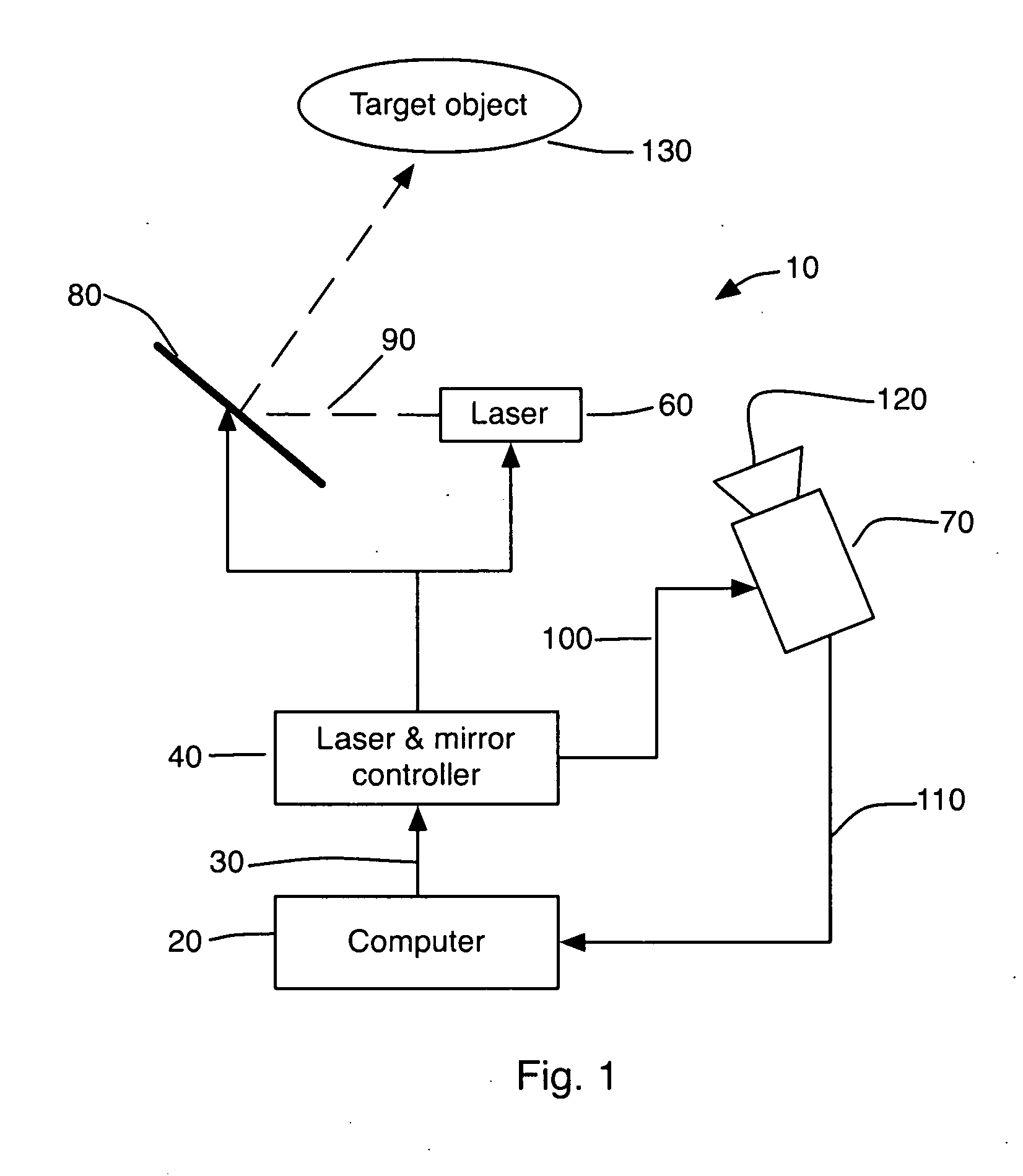
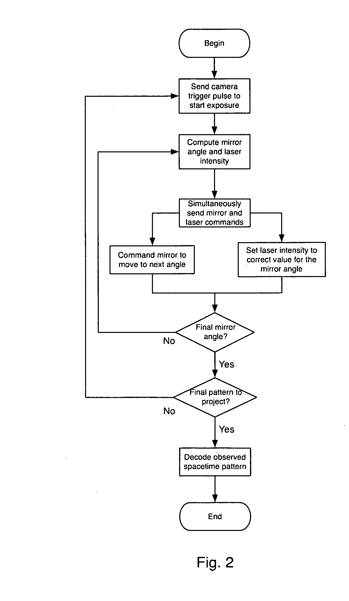
[0031]In the following detailed description, reference is made to the accompanying examples and figures that form a part hereof, and in which is shown by way of illustration specific embodiments in which the inventive subject matter may be practiced. These embodiments are described in sufficient detail to enable those skilled in the art to practice them, and it is to be understood that other embodiments may be utilized and that structural, logical, and electrical changes may be made without departing from the scope of the inventive subject matter. Such embodiments of the inventive subject matter may be referred to, individually and / or collectively, herein by the term “invention” merely for convenience and without intending to voluntarily limit the scope of this application to any single invention or inventive concept if more than one is in fact disclosed.

[0032]The following description is, therefore, not to be taken in a limited sense, and the scope of the inventive subject matter i...


PUM


Abstract

A desktop three-dimensional imaging system and method projects a modulated plane of light that sweeps across a target object while a camera is set to collect an entire pass of the modulated plane of light over the object in one image to create a line stripe pattern. A spacetime coding scheme is applied to the modulation controller whereby a plurality of images of line stripe patterns can be analyzed and decoded to yield a three-dimensional image of the target object in a reduced scan time and with better accuracy than existing close range scanners.

Description

CROSS REFERENCE TO RELATED APPLICATIONS[0001]This application claims the benefit of U.S. Provisional App. No. 61 / 070,086, filed Mar. 20, 2008, the disclosure of which is incorporated by reference in its entirety.BACKGROUND OF THE INVENTION[0002]The present invention generally relates to a method and apparatus for three-dimensional (“3D”) shape measurement using a spacetime coded, structured light laser projection system. More specifically, the invention relates to a “desktop 3D scanner” that is small enough to fit on a conventional table or desk, connects directly to a laptop computer or workstation, integrates with a 3D modeling or CAD application, and dramatically reduces the time required to build a 3D model of an object.[0003]3D imaging systems are widely used for acquiring the shape of an object for purposes of reverse engineering, rapid prototyping, computer game and film animation, graphic design, industrial process control, medical analysis, and numerous other fields. Prior ...

Claims


Application Information

Patent Timeline
Patent Type & Authority Applications(United States)
IPC IPC(8): H04N13/02G06T15/00
CPCG01B11/2513H04N13/0253H04N13/0207G01B11/2527H04N13/207H04N13/254
Inventor SHELTON, DAMION M.FORMICA, MICLE K.
Owner THREERIVERS 3D
Learn More